
Instruction Manual
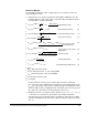
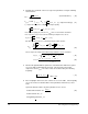


Table Of Contents
- S-3056-1 Distributed Power System SA3100 Drive Configuration and Programming Instruction Manual
- Important User Information
- Contents
- List of Figures
- List of Tables
- Chapter 1 Introduction
- Chapter 2 Configuring the UDC Module, Regulator Type, and Parameters
- 2.1 Adding a Universal Drive Controller (UDC) Module
- 2.2 Entering the Drive Parameters
- 2.3 Configuring the Vector with Constant Power Regulator
- 2.4 Configuring the Volts per Hertz (V/Hz) Regulator
- 2.5 Configuring Flex I/O
- 2.6 Generating Drive Parameter Files and Printing Drive Parameters
- Chapter 3 Configuring the UDC Module’s Registers
- 3.1 Register and Bit Reference Conventions Used in this Manual
- 3.2 Flex I/O Port Registers (Registers 0-23)
- 3.3 UDC/PMI Communication Status Registers (Registers 80-89/1080-1089)
- 3.4 Command Registers (Registers 100-199/1100-1199)
- 3.5 Feedback Registers (Registers 200-299/1200-1299)
- 3.6 Application Registers (Registers 300-599, Every Scan) (Registers 1300-1599, Every Nth Scan)
- 3.7 UDC Module Test I/O Registers (Registers 1000-1017)
- 3.8 Interrupt Status and Control Registers (Registers 2000-2047)
- Chapter 4 Application Programming for DPS Drive Control
- Chapter 5 On-Line Operation
- Appendix A SA3100 Vector Regulator Register Reference
- Appendix B SA3100 Volts / Hertz Regulator Register Reference
- Appendix C SA3100 Local Tunable Variables
- Appendix D Vector with Constant Power Regulator
- Appendix E Volts per Hertz (V/Hz) Regulator
- Appendix F Status of Data in the AutoMax Rack After a STOP_ALL Command or STOP_ALL Fault
- Appendix G Torque Overload Ratio Parameter Precautions
- Appendix H Default Carrier Frequency and Carrier Frequency Limit for Drive Horsepower Ranges
- Appendix I Vector with Constant Power Parameter Entry Example
- Index

J-4 Drive Configuration and Programming
For a 2 to 1 range; reference points one, two, three, four, five, six and seven are
used.
For a 3 to 1 range; reference points eight and nine are also used.
For a 4 to 1 range; reference point ten is also used.
Note that PMI operating system version requires internal gain tunables IGN1! to
IGN9! for retention of the table data.
(IGN ==> Internal Gain)
Use the following procedure to implement each reference point in the speed loop
calculation:
Step 1. With the drive’s motor unconnected, set bits 0 and 1 of register 101/1101.
Register 101 is for Drive A and register 1101 is for Drive B. Drive B can be
setup by using the register number for Drive A plus 1000.
The following steps will use Drive A for this example.
Step 2. Command the speed loop to the appropriate speed reference.
Step 3. When the speed is reached, set bit 10 of register 101 in the UDC.
Step 4. Monitor register 203 and bit 10 of register 201.
Step 5. If register 203 is set to hex 20, reset bit 10 of register 101 and go to step 7.
Step 6. If bit 10 of register 201 was set, reset bit 10 in register 101 and continue with
the next speed point as described in step 3. When all the required speed
points have been completed, go to step 8.
Step 7. If register 203 contains a hex value of 20, verify that the speed scaling of the
speed loop is correct and refer to the Notes at the end of this appendix. Reset
the warning, and continue with the next speed point as described in step 3.
Step 8. Reset bits 0 and 1 of register 101.
Note: The values saved in the IGNn! variables will be in (amps*100) units.
Note that in Dual Wound Motor Applications (Parallel Inverter Drives) you must
use the procedure described above with the following additions:
• After using the reference point data for Drive A (register 101), use the
reference point data for Drive B register (1101).
• Ensure that the vector orientation alignment request bit (bit 6, 0040h) is set in
register 1100.
• The IGNn! values for the A and B drives should be the same. The acquisition
of data should be done with both drives to verify that the magnitudes of the
values are similar. After the acquisition is done, the IGNn! values from Drive
A should be used for Drive B.