
Instruction Manual
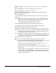
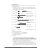
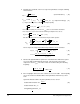
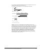


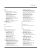
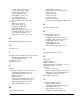
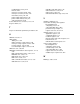

Table Of Contents
- S-3056-1 Distributed Power System SA3100 Drive Configuration and Programming Instruction Manual
- Important User Information
- Contents
- List of Figures
- List of Tables
- Chapter 1 Introduction
- Chapter 2 Configuring the UDC Module, Regulator Type, and Parameters
- 2.1 Adding a Universal Drive Controller (UDC) Module
- 2.2 Entering the Drive Parameters
- 2.3 Configuring the Vector with Constant Power Regulator
- 2.4 Configuring the Volts per Hertz (V/Hz) Regulator
- 2.5 Configuring Flex I/O
- 2.6 Generating Drive Parameter Files and Printing Drive Parameters
- Chapter 3 Configuring the UDC Module’s Registers
- 3.1 Register and Bit Reference Conventions Used in this Manual
- 3.2 Flex I/O Port Registers (Registers 0-23)
- 3.3 UDC/PMI Communication Status Registers (Registers 80-89/1080-1089)
- 3.4 Command Registers (Registers 100-199/1100-1199)
- 3.5 Feedback Registers (Registers 200-299/1200-1299)
- 3.6 Application Registers (Registers 300-599, Every Scan) (Registers 1300-1599, Every Nth Scan)
- 3.7 UDC Module Test I/O Registers (Registers 1000-1017)
- 3.8 Interrupt Status and Control Registers (Registers 2000-2047)
- Chapter 4 Application Programming for DPS Drive Control
- Chapter 5 On-Line Operation
- Appendix A SA3100 Vector Regulator Register Reference
- Appendix B SA3100 Volts / Hertz Regulator Register Reference
- Appendix C SA3100 Local Tunable Variables
- Appendix D Vector with Constant Power Regulator
- Appendix E Volts per Hertz (V/Hz) Regulator
- Appendix F Status of Data in the AutoMax Rack After a STOP_ALL Command or STOP_ALL Fault
- Appendix G Torque Overload Ratio Parameter Precautions
- Appendix H Default Carrier Frequency and Carrier Frequency Limit for Drive Horsepower Ranges
- Appendix I Vector with Constant Power Parameter Entry Example
- Index
Commissioning Procedure for Non-Constant Power Algorithim Operation J-5
Reference Material -
The following information describes step by step processor functions for the new
commissioning procedure.
1. Calculate the necessary motor parameters and variables initially based on the
following equations: (This represents the action taken when the PMI tune function
is invoked (bit 1 of register 100/1100)).
1.
1.
1.
1.
1.
1.
1.
1.
1.
1.
1.
1.
1.
1.
1.
1.
1.
1.
1.
1.
1.
1.
2. Run the algorithm with the closed flux loop using the flux reference (4) directly in
the final stator flux reference point. Run the drive at the 40% speed point.
The result of this step is obtaining the first iteration of a rated magnetizing current
I
z_rtd_1
by measuring an output of a flux regulator through an averaging procedure
(at least a 1000 scan time sampling interval). Recalculate expression (2), (3), and
(5) - (9) based on new value of the flux producing current I
z_rtd_1.
3. Disable the flux loop. Set output of a flux regulator. Id_ref = √2⋅Ι
z _ rtd _ 1
= I
d _ rtd
_ 1.
Run drive on a synchronous speed with no load condition and make a
measurement of motor voltage through an averaging procedure (at least a 1000
scan time sampling interval). This motor voltage is a rated no load motor voltage
V
NL _ rtd.
I
z_rtd_start
(amps) = 3
.
I
st _ rtd
746 * HP
rtd
V
mot _ rtd
(magnetizing current) ( 1 )
I
d_rtd_start
(amps) = 2
.
I
z _ rtd_start
(flux producing current) ( 2 )
I
q_rtd_start
(amps) = 2
.
I
2
st _ rtd
_
I
2
d _ rtd _ start
(torque producing current) ( 3 )
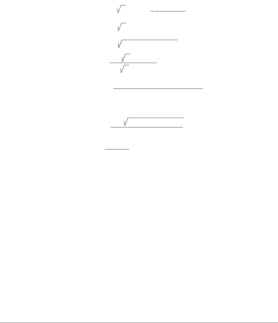
Ψ
ref_start
(wb) =
0.97
.
2
.
V
mot _ rtd
3
.
2
.
π
.
f
0
(stator flux reference)
( 4 )
R
r0_start
(ohms) = 551 . HP
rtd
. (RPM
synch
- RPM
rtd
)
RPM
rtd
.
I
2
q_rtd_start
R
st0_start
(ohms) = 1.3
.
R
r0_ start
(rotor resistor for the
rated temperature)
(stator resistor for the rated
( 5 )
temperature)
( 6 )
Ψ
r_rtd_start
(wb) =
227
.
HP
rtd
.
V
mot_rtd
.
I
st_rtd
p
.
RPM
rtd
.
Ι
q _ rtd _ start
(rated rotor flux)
( 7 )
L
m0_start
(H) =
Ψ
r_rtd_start
Ι
d _ rtd _ start
(mutual inductance)
( 8 )
L*
σs _ start
= 0.05 . L
m0 _ start (modified leakage inductance) ( 9 )
where:
HP
rtd
- Motor rated horsepower
V
mot_rtd
- Rated motor line - to - line voltage (RMS)
I
st_rtd
- Rated motor phase stator current (RMS)
f
0
- Rated stator frequency (Hz)
p - pole pairs