
Instruction Manual
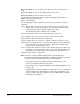
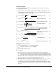
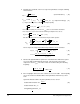
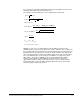


Table Of Contents
- S-3056-1 Distributed Power System SA3100 Drive Configuration and Programming Instruction Manual
- Important User Information
- Contents
- List of Figures
- List of Tables
- Chapter 1 Introduction
- Chapter 2 Configuring the UDC Module, Regulator Type, and Parameters
- 2.1 Adding a Universal Drive Controller (UDC) Module
- 2.2 Entering the Drive Parameters
- 2.3 Configuring the Vector with Constant Power Regulator
- 2.4 Configuring the Volts per Hertz (V/Hz) Regulator
- 2.5 Configuring Flex I/O
- 2.6 Generating Drive Parameter Files and Printing Drive Parameters
- Chapter 3 Configuring the UDC Module’s Registers
- 3.1 Register and Bit Reference Conventions Used in this Manual
- 3.2 Flex I/O Port Registers (Registers 0-23)
- 3.3 UDC/PMI Communication Status Registers (Registers 80-89/1080-1089)
- 3.4 Command Registers (Registers 100-199/1100-1199)
- 3.5 Feedback Registers (Registers 200-299/1200-1299)
- 3.6 Application Registers (Registers 300-599, Every Scan) (Registers 1300-1599, Every Nth Scan)
- 3.7 UDC Module Test I/O Registers (Registers 1000-1017)
- 3.8 Interrupt Status and Control Registers (Registers 2000-2047)
- Chapter 4 Application Programming for DPS Drive Control
- Chapter 5 On-Line Operation
- Appendix A SA3100 Vector Regulator Register Reference
- Appendix B SA3100 Volts / Hertz Regulator Register Reference
- Appendix C SA3100 Local Tunable Variables
- Appendix D Vector with Constant Power Regulator
- Appendix E Volts per Hertz (V/Hz) Regulator
- Appendix F Status of Data in the AutoMax Rack After a STOP_ALL Command or STOP_ALL Fault
- Appendix G Torque Overload Ratio Parameter Precautions
- Appendix H Default Carrier Frequency and Carrier Frequency Limit for Drive Horsepower Ranges
- Appendix I Vector with Constant Power Parameter Entry Example
- Index
J-6 Drive Configuration and Programming
4. Calculate the remainder of the necessary motor parameters using the following
measurements:
5. Run the full algorithm with the parameters calculated above with flux loop and
access the table starting with the first point. The first point is the rated d-
component current I
d_rtd
. The value of this current must satisfy the following
inequality:
6. If the inequality in #17 is true, then continue to access the table. If the inequality
(17) is not true then recalculate all the motor parameters with new I
d_rtd
and
rerun.
System architecture allows only three parameters to be saved.
L
s0
=
2 V
NL_rtd
V
2
mot _ rtd
(stator inductance)
( 10 )
I
d_rtd_1
(q - component voltage) ( 11 )
V
q_rtd
= OLR
.
I
q _ rtd _ 1
R
st _1
+
2
.
π
.
f
0
( 12 )
R
st_1
OLR
.
I
q _ rtd
_
1
V
d_rtd
_ 1
( 16 )
=
=
( 14 )
.
.
.
2
3
.
V
NL _ rtd
q - component voltage has to satisfy the following inequality:
2
3
.
V
mot _ rtd
V
q _ rtd
> 2
If the above inequality (12) is true then V
q_rtd
can be used for further calculations.
If the expression (12) is not true then the following assumption has to be set:
( 15 )
2
3
V
mot _ rtd
V
mot _ rtd
V
q_rtd
=
V
NL _ rtd
.
( 13 )2.5
and stator resistance has to be recalculated using the follow equation:
2
3
(
)
2
3
2.5
.
Then d-component voltage and modified leakage inductance can be calculated:
2
3
.
V
2
q _ rtd _ 1
L*
σs 0
=
V
d _ rtd _ 1
+ I
d _ rtd _ 1
.
R
st _ 1
2
.
π
.
f
0
OLR
.
I
q _ rtd
_
1
.
( 17 )
I
d_rtd -
I
d _ rtd _ 1
I
d _ rtd
.
100% < 2%
( 18 )
● stator time constant:
T
st
=
L*
σs 0
R
st _ rtd
● stator resistor:
R
st _ rtd
● magnetizing current:
I
z _ rtd