
Instruction Manual
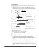
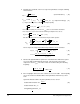
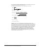


Table Of Contents
- S-3056-1 Distributed Power System SA3100 Drive Configuration and Programming Instruction Manual
- Important User Information
- Contents
- List of Figures
- List of Tables
- Chapter 1 Introduction
- Chapter 2 Configuring the UDC Module, Regulator Type, and Parameters
- 2.1 Adding a Universal Drive Controller (UDC) Module
- 2.2 Entering the Drive Parameters
- 2.3 Configuring the Vector with Constant Power Regulator
- 2.4 Configuring the Volts per Hertz (V/Hz) Regulator
- 2.5 Configuring Flex I/O
- 2.6 Generating Drive Parameter Files and Printing Drive Parameters
- Chapter 3 Configuring the UDC Module’s Registers
- 3.1 Register and Bit Reference Conventions Used in this Manual
- 3.2 Flex I/O Port Registers (Registers 0-23)
- 3.3 UDC/PMI Communication Status Registers (Registers 80-89/1080-1089)
- 3.4 Command Registers (Registers 100-199/1100-1199)
- 3.5 Feedback Registers (Registers 200-299/1200-1299)
- 3.6 Application Registers (Registers 300-599, Every Scan) (Registers 1300-1599, Every Nth Scan)
- 3.7 UDC Module Test I/O Registers (Registers 1000-1017)
- 3.8 Interrupt Status and Control Registers (Registers 2000-2047)
- Chapter 4 Application Programming for DPS Drive Control
- Chapter 5 On-Line Operation
- Appendix A SA3100 Vector Regulator Register Reference
- Appendix B SA3100 Volts / Hertz Regulator Register Reference
- Appendix C SA3100 Local Tunable Variables
- Appendix D Vector with Constant Power Regulator
- Appendix E Volts per Hertz (V/Hz) Regulator
- Appendix F Status of Data in the AutoMax Rack After a STOP_ALL Command or STOP_ALL Fault
- Appendix G Torque Overload Ratio Parameter Precautions
- Appendix H Default Carrier Frequency and Carrier Frequency Limit for Drive Horsepower Ranges
- Appendix I Vector with Constant Power Parameter Entry Example
- Index

Commissioning Procedure for Non-Constant Power Algorithim Operation J-7
It is necessary to recalculate all algorithm coefficients and variables based on motor
nameplate data and the above three parameters.
The equation set which allows this to be accomplished is shown below:
NOTES: In some cases, the approximation from the PMI tune function for the
STATOR_IZ_E1% value causes the flux loop to go into saturation. This condition can
be recognized if the tune abort warning occurs immediately upon asserting the tune iz
bit when at the first speed point. To compensate for this condition, the operator can
observe the Flux Reference and Flux Feedback signals via the power module meter
ports. The digitized value for the fourth port is available to a register (219 / 1219 -
SEL_VAR%). The value of STATOR_IZ_E1% can be modified online until the
reference and feedback are approximately equal. When the two signals are
approximately equal, the value of “Id current reference counts” (observed via the
power module meter ports) should be changing. When this state is acheived, the
commissioning procedure may continue.
I
d_rtd
=
2 I
z_rtd
I
q_rtd
=
2
R
st_0
=
R
st_rtd
.
.
I
2
st_rtd
(RPM
synch
- RPM
rtd
)
551 HP
rtd
L
m 0
=
I
2
d_rtd
R
r 0
=
R
r_rtd
=
. .
RPM
rtd
- I
2
q
_ rtd
Ψ
r_rtd_start
(wb) =
227
HP
rtd
.
V
mot_rtd
.
I
st_rtd
p
.
RPM
rtd
.
Ι
q _ rtd
.
Ψ
r_rtd
I
d_rtd
L*
σs 0
= T
st
.
R
st_rtd
L
s 0
= L
r 0
= L
m 0
+ L*
σs 0