
Instruction Manual
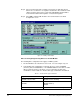
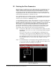
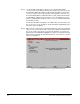
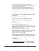
Table Of Contents
- S-3056-1 Distributed Power System SA3100 Drive Configuration and Programming Instruction Manual
- Important User Information
- Contents
- List of Figures
- List of Tables
- Chapter 1 Introduction
- Chapter 2 Configuring the UDC Module, Regulator Type, and Parameters
- 2.1 Adding a Universal Drive Controller (UDC) Module
- 2.2 Entering the Drive Parameters
- 2.3 Configuring the Vector with Constant Power Regulator
- 2.4 Configuring the Volts per Hertz (V/Hz) Regulator
- 2.5 Configuring Flex I/O
- 2.6 Generating Drive Parameter Files and Printing Drive Parameters
- Chapter 3 Configuring the UDC Module’s Registers
- 3.1 Register and Bit Reference Conventions Used in this Manual
- 3.2 Flex I/O Port Registers (Registers 0-23)
- 3.3 UDC/PMI Communication Status Registers (Registers 80-89/1080-1089)
- 3.4 Command Registers (Registers 100-199/1100-1199)
- 3.5 Feedback Registers (Registers 200-299/1200-1299)
- 3.6 Application Registers (Registers 300-599, Every Scan) (Registers 1300-1599, Every Nth Scan)
- 3.7 UDC Module Test I/O Registers (Registers 1000-1017)
- 3.8 Interrupt Status and Control Registers (Registers 2000-2047)
- Chapter 4 Application Programming for DPS Drive Control
- Chapter 5 On-Line Operation
- Appendix A SA3100 Vector Regulator Register Reference
- Appendix B SA3100 Volts / Hertz Regulator Register Reference
- Appendix C SA3100 Local Tunable Variables
- Appendix D Vector with Constant Power Regulator
- Appendix E Volts per Hertz (V/Hz) Regulator
- Appendix F Status of Data in the AutoMax Rack After a STOP_ALL Command or STOP_ALL Fault
- Appendix G Torque Overload Ratio Parameter Precautions
- Appendix H Default Carrier Frequency and Carrier Frequency Limit for Drive Horsepower Ranges
- Appendix I Vector with Constant Power Parameter Entry Example
- Index
2-6
SA3100 Drive Configuration and Programming
Power Module
• Part Number
Select a part number from the list of supported Power modules (
x nnn
, where x is
the voltage code and nnn is the horsepower rating). The current ratings in the list
are the rated RMS currents at the drive’s default carrier frequency as listed in
Appendix H, with no overload at 40° ambient temperature. The power module is
capable of 150% of the maximum amps value for 1 minute. There is no default
selection. You must choose a part number from the list.
The motor must be able to operate off the Power Module selected at the voltage
level entered as the Input Voltage parameter. A warning will be issued when if an
incompatibility is found.
• Carrier Frequency
The carrier frequency selected will determine the Power Module’s switching
frequency. You can select from a list of preset carrier frequencies: 1.5 kHz, 2 kHz, 4
kHz, 6 kHz, 8 kHz, 10 kHz or 12 kHz; or you can enter a value between 1.5 kHz and
12 kHz in increments of 100 Hz. The hardware in some cases will have slightly
coarser resolution at the higher frequencies. See Appendix H for the default carrier
frequency and carrier frequency limit for the Power Module you have selected.
All Power Modules are rated at their default switching frequency, but they can be
operated above this limit by de-rating the unit’s output. Refer to the SA3100 Power
Modules instruction manual (S-3058) for more information.
2.3.2 Motor Data Screen (Vector with Constant Power)
The Motor Data parameter screen allows you to enter specific information about the
motor you are using. (If you are using a high slip motor, see Appendix B for additional
information.) See figure 2.5.
Figure 2.5 – Motor Data Parameter Entry Screen used for Constant Magnetization or Manual
Compensation