
Instruction Manual
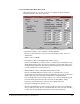
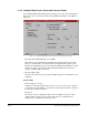
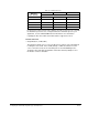
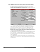
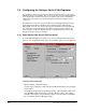
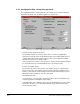
Table Of Contents
- S-3056-1 Distributed Power System SA3100 Drive Configuration and Programming Instruction Manual
- Important User Information
- Contents
- List of Figures
- List of Tables
- Chapter 1 Introduction
- Chapter 2 Configuring the UDC Module, Regulator Type, and Parameters
- 2.1 Adding a Universal Drive Controller (UDC) Module
- 2.2 Entering the Drive Parameters
- 2.3 Configuring the Vector with Constant Power Regulator
- 2.4 Configuring the Volts per Hertz (V/Hz) Regulator
- 2.5 Configuring Flex I/O
- 2.6 Generating Drive Parameter Files and Printing Drive Parameters
- Chapter 3 Configuring the UDC Module’s Registers
- 3.1 Register and Bit Reference Conventions Used in this Manual
- 3.2 Flex I/O Port Registers (Registers 0-23)
- 3.3 UDC/PMI Communication Status Registers (Registers 80-89/1080-1089)
- 3.4 Command Registers (Registers 100-199/1100-1199)
- 3.5 Feedback Registers (Registers 200-299/1200-1299)
- 3.6 Application Registers (Registers 300-599, Every Scan) (Registers 1300-1599, Every Nth Scan)
- 3.7 UDC Module Test I/O Registers (Registers 1000-1017)
- 3.8 Interrupt Status and Control Registers (Registers 2000-2047)
- Chapter 4 Application Programming for DPS Drive Control
- Chapter 5 On-Line Operation
- Appendix A SA3100 Vector Regulator Register Reference
- Appendix B SA3100 Volts / Hertz Regulator Register Reference
- Appendix C SA3100 Local Tunable Variables
- Appendix D Vector with Constant Power Regulator
- Appendix E Volts per Hertz (V/Hz) Regulator
- Appendix F Status of Data in the AutoMax Rack After a STOP_ALL Command or STOP_ALL Fault
- Appendix G Torque Overload Ratio Parameter Precautions
- Appendix H Default Carrier Frequency and Carrier Frequency Limit for Drive Horsepower Ranges
- Appendix I Vector with Constant Power Parameter Entry Example
- Index

Configuring the UDC Module, Regulator Type, and Parameters
2-11
If a warning appears, it is likely that the maximum RMS current that can be supplied
to the motor at the torque overload ratio level selected is too high for the Power
Module selected. See Appendix E for more information on determining the
maximum RMS current that will result from the ratio entered.
Base: Enter the base (rated) torque overload ratio.
O1-O4: Enter the additional overload ratios at each speed, S1 to S4. This
information is located on the motor design data sheet.
• Frequency at Rated Voltage (Hz) (Range: 1 to 400)
This value is used to determine the frequency at which the motor enters the
constant power range. Enter the value in Hz * 10. The resolution is 0.1 Hz. There
is no default value.
• Motor Poles (2, 4, 6, 8, 10, 12, 14, or 16)
This value is used to determine the relationship between drive output frequency
and motor shaft speed. Because this number is not readily available, the number of
motor poles will be calculated automatically based on the other parameters you
have entered and will be displayed on the screen. You must then select this
calculated value from a list of the preset values. There is no default value.
The following formula will be used to calculate the number of motor poles:
120
∗
Frequency at Rated Voltage
÷
Rated Full Load Speed
The resulting number will be rounded down to the nearest whole even number.
Note that this formula may not result in the correct number of motor poles if you are
using a high slip motor, such as a NEMA design D motor. See table 2.2 for the
maximum slip per number of motor poles that will result in a correct calculation.