
Instruction Manual
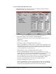
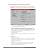
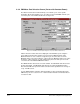
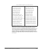
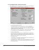
Table Of Contents
- S-3056-1 Distributed Power System SA3100 Drive Configuration and Programming Instruction Manual
- Important User Information
- Contents
- List of Figures
- List of Tables
- Chapter 1 Introduction
- Chapter 2 Configuring the UDC Module, Regulator Type, and Parameters
- 2.1 Adding a Universal Drive Controller (UDC) Module
- 2.2 Entering the Drive Parameters
- 2.3 Configuring the Vector with Constant Power Regulator
- 2.4 Configuring the Volts per Hertz (V/Hz) Regulator
- 2.5 Configuring Flex I/O
- 2.6 Generating Drive Parameter Files and Printing Drive Parameters
- Chapter 3 Configuring the UDC Module’s Registers
- 3.1 Register and Bit Reference Conventions Used in this Manual
- 3.2 Flex I/O Port Registers (Registers 0-23)
- 3.3 UDC/PMI Communication Status Registers (Registers 80-89/1080-1089)
- 3.4 Command Registers (Registers 100-199/1100-1199)
- 3.5 Feedback Registers (Registers 200-299/1200-1299)
- 3.6 Application Registers (Registers 300-599, Every Scan) (Registers 1300-1599, Every Nth Scan)
- 3.7 UDC Module Test I/O Registers (Registers 1000-1017)
- 3.8 Interrupt Status and Control Registers (Registers 2000-2047)
- Chapter 4 Application Programming for DPS Drive Control
- Chapter 5 On-Line Operation
- Appendix A SA3100 Vector Regulator Register Reference
- Appendix B SA3100 Volts / Hertz Regulator Register Reference
- Appendix C SA3100 Local Tunable Variables
- Appendix D Vector with Constant Power Regulator
- Appendix E Volts per Hertz (V/Hz) Regulator
- Appendix F Status of Data in the AutoMax Rack After a STOP_ALL Command or STOP_ALL Fault
- Appendix G Torque Overload Ratio Parameter Precautions
- Appendix H Default Carrier Frequency and Carrier Frequency Limit for Drive Horsepower Ranges
- Appendix I Vector with Constant Power Parameter Entry Example
- Index

Configuring the UDC Module, Regulator Type, and Parameters
2-15
PMI meter ports can also be set up on-line using the “Setup UDC” selection from the
Monitor menu as described in the AutoMax Programming Executive instruction
manual. If the meter ports are set up during parameter entry, the information is loaded
onto the UDC module in the AutoMax rack along with all other parameter data. The
meter port setup can then be changed on-line under “Setup UDC,” but this method
would not actually write over the PMI meter port setup that was loaded to the rack.
Instead, the new setup would be valid only until there was a Stop All or a power cycle,
in which case the original setup would be used to determine what data to send out of
the meter ports.
Table 2.4 – PMI Meter Port Parameters (Vector with Constant Power)
• Port Not Used
• Torque Reference (Counts)
• Torque Feedback (Counts)
• Flux Reference (Counts)
• Flux Feedback (Counts)
• DC Bus Voltage (Volts)
• DC Bus Current (Amps
∗
10)
• Ground Fault Current (Amps
∗
10)
• Motor Voltage Feedback (Volts)
• Motor Current Feedback ( Amps
∗
10 )
• Id Current Reference (Counts)
• Id Current Feedback (Counts)
• Vd Reference (Counts)
• Iq Current Reference (Counts)
• Iq Current Feedback (Counts)
• Vq Reference (Counts)
• Slip Frequency (Hz
∗
100)
• Output Frequency (Hz
∗
10)
• User Analog Input (Counts)
• Speed Feedback (RPM)
• Application Data (Units)
• Flex Module 0 (Counts)
• Flex Module 1 (Counts)
• Flex Module 2 Channel 0 (Counts)
• Flex Module 2 Channel 1 (Counts)
• Flex Module 2 Channel 2 (Counts)
• Flex Module 2 Channel 3 (Counts)
• Flex Module 2 Channel 4 (Counts)
• Power Module Heat Sink Temp (°C)