
Instruction Manual
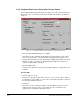
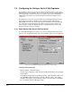
Table Of Contents
- S-3056-1 Distributed Power System SA3100 Drive Configuration and Programming Instruction Manual
- Important User Information
- Contents
- List of Figures
- List of Tables
- Chapter 1 Introduction
- Chapter 2 Configuring the UDC Module, Regulator Type, and Parameters
- 2.1 Adding a Universal Drive Controller (UDC) Module
- 2.2 Entering the Drive Parameters
- 2.3 Configuring the Vector with Constant Power Regulator
- 2.4 Configuring the Volts per Hertz (V/Hz) Regulator
- 2.5 Configuring Flex I/O
- 2.6 Generating Drive Parameter Files and Printing Drive Parameters
- Chapter 3 Configuring the UDC Module’s Registers
- 3.1 Register and Bit Reference Conventions Used in this Manual
- 3.2 Flex I/O Port Registers (Registers 0-23)
- 3.3 UDC/PMI Communication Status Registers (Registers 80-89/1080-1089)
- 3.4 Command Registers (Registers 100-199/1100-1199)
- 3.5 Feedback Registers (Registers 200-299/1200-1299)
- 3.6 Application Registers (Registers 300-599, Every Scan) (Registers 1300-1599, Every Nth Scan)
- 3.7 UDC Module Test I/O Registers (Registers 1000-1017)
- 3.8 Interrupt Status and Control Registers (Registers 2000-2047)
- Chapter 4 Application Programming for DPS Drive Control
- Chapter 5 On-Line Operation
- Appendix A SA3100 Vector Regulator Register Reference
- Appendix B SA3100 Volts / Hertz Regulator Register Reference
- Appendix C SA3100 Local Tunable Variables
- Appendix D Vector with Constant Power Regulator
- Appendix E Volts per Hertz (V/Hz) Regulator
- Appendix F Status of Data in the AutoMax Rack After a STOP_ALL Command or STOP_ALL Fault
- Appendix G Torque Overload Ratio Parameter Precautions
- Appendix H Default Carrier Frequency and Carrier Frequency Limit for Drive Horsepower Ranges
- Appendix I Vector with Constant Power Parameter Entry Example
- Index
2-18
SA3100 Drive Configuration and Programming
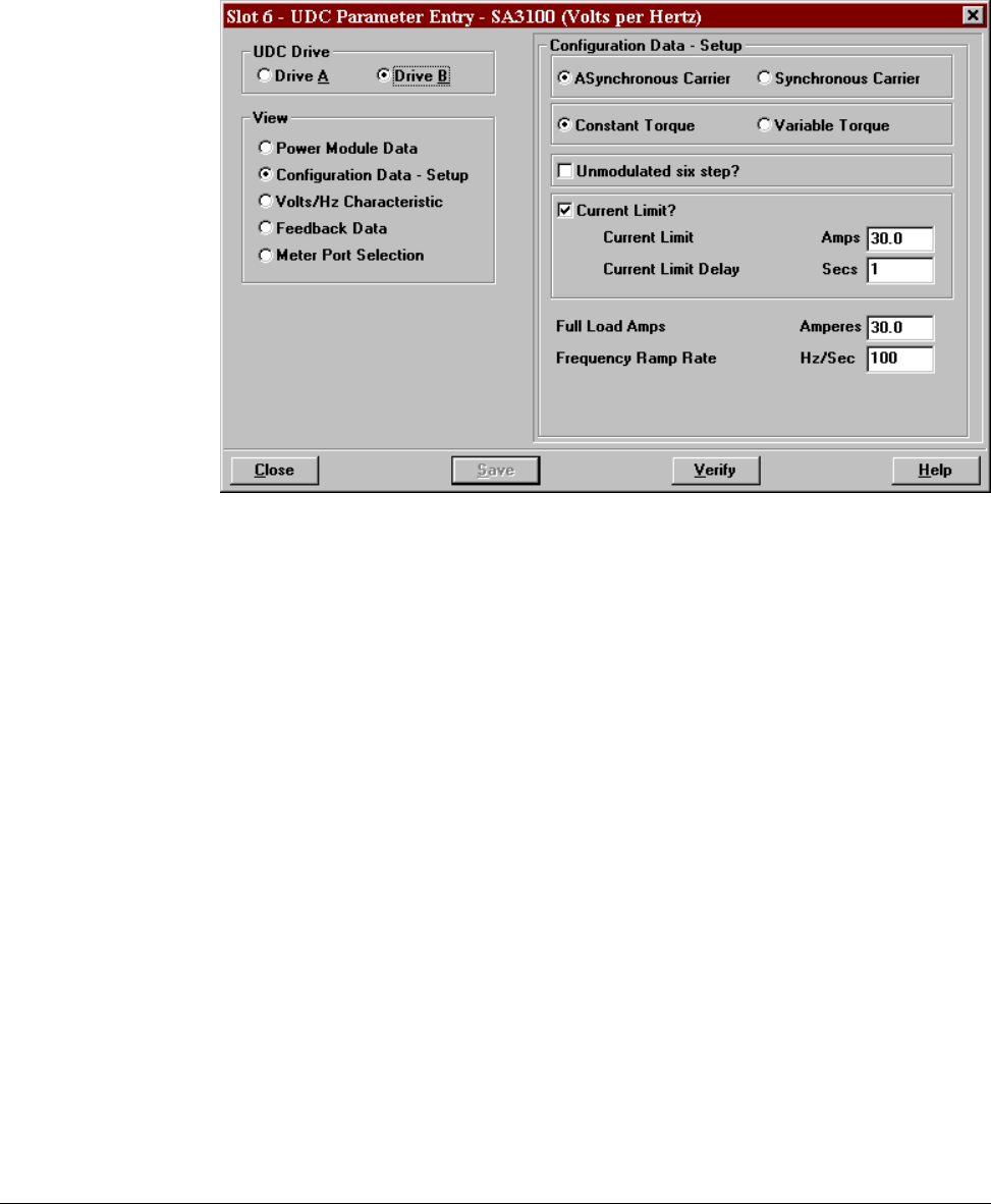
2.4.2 Configuration Data - Setup (Volts per Hertz)
The Configuration Data - Setup parameter screen allows you to enter the following
information about the Volts per Hertz regulator. See figure 2.10.
• Asynchronous or Synchronous Carrier
The default is asynchronous carrier, which can be used for most applications.
Synchronous mode provides synchronization between the fundamental frequency
output from the drive and the carrier frequency. This causes minimal circulating
currents when inverters are swiched online.
Select Synchronous Carrier to cause the drive to synchronize the fundamental and
the carrier whenever the commanded frequency is greater than 15 Hz.
• Constant or Variable Torque
These buttons provide for the selection of the variable torque or constant torque
volts per hertz curve. The default is Constant Torque. When the Variable Torque
button is selected, the Constant Voltage Frequency, Motor Rated Frequency, and
Maximum Frequency fields are set to the same point.
• Unmodulated Six Step
Use this button to select the option of having the drive output an unmodulated six
step waveform when at maximum output voltage.
Unmodulated six step is defined as the lack of any modulating pulses in the output
waveform of the drive. Users who want maximum voltage output from the drive
should select this option.
Figure 2.10 – Configuration Data Setup Parameter Entry Screen (Volts per Hertz)