
Instruction Manual
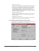
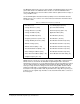
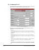
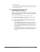

Table Of Contents
- S-3056-1 Distributed Power System SA3100 Drive Configuration and Programming Instruction Manual
- Important User Information
- Contents
- List of Figures
- List of Tables
- Chapter 1 Introduction
- Chapter 2 Configuring the UDC Module, Regulator Type, and Parameters
- 2.1 Adding a Universal Drive Controller (UDC) Module
- 2.2 Entering the Drive Parameters
- 2.3 Configuring the Vector with Constant Power Regulator
- 2.4 Configuring the Volts per Hertz (V/Hz) Regulator
- 2.5 Configuring Flex I/O
- 2.6 Generating Drive Parameter Files and Printing Drive Parameters
- Chapter 3 Configuring the UDC Module’s Registers
- 3.1 Register and Bit Reference Conventions Used in this Manual
- 3.2 Flex I/O Port Registers (Registers 0-23)
- 3.3 UDC/PMI Communication Status Registers (Registers 80-89/1080-1089)
- 3.4 Command Registers (Registers 100-199/1100-1199)
- 3.5 Feedback Registers (Registers 200-299/1200-1299)
- 3.6 Application Registers (Registers 300-599, Every Scan) (Registers 1300-1599, Every Nth Scan)
- 3.7 UDC Module Test I/O Registers (Registers 1000-1017)
- 3.8 Interrupt Status and Control Registers (Registers 2000-2047)
- Chapter 4 Application Programming for DPS Drive Control
- Chapter 5 On-Line Operation
- Appendix A SA3100 Vector Regulator Register Reference
- Appendix B SA3100 Volts / Hertz Regulator Register Reference
- Appendix C SA3100 Local Tunable Variables
- Appendix D Vector with Constant Power Regulator
- Appendix E Volts per Hertz (V/Hz) Regulator
- Appendix F Status of Data in the AutoMax Rack After a STOP_ALL Command or STOP_ALL Fault
- Appendix G Torque Overload Ratio Parameter Precautions
- Appendix H Default Carrier Frequency and Carrier Frequency Limit for Drive Horsepower Ranges
- Appendix I Vector with Constant Power Parameter Entry Example
- Index

Configuring the UDC Module, Regulator Type, and Parameters
2-19
• Current Limit
Selecting this button enables the current limit function in the drive. Specify the
limiting current value in the Current Limit Amps field. Resolution is 0.1 amp.
• Current Limit Delay
Current Limit Delay provides a time delay for the drive to operate in the current limit
region before executing the current limiting functions. If the regulator detects that
output current has reached the specified limit, it will respond by setting bit 2 or 3 in
register 204/1204. After the specified time delay, the regulator will set bit 4 in
register 203/1203 (WRN_RIL@) and begin modifying the output frequency. Enter
the value in seconds.
• Full Load Amps (Amperes)
Enter the default rated motor current. Resolution is 0.1 amp.
• Frequency Ramp Rate (Hertz/Second)
Frequency Ramp Rate specifies an adjustable limit for the maximum allowable rate
of change in the frequency output. Enter the value in hertz per second.