
Instruction Manual
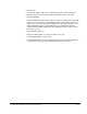
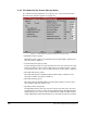
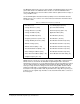
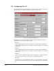
Table Of Contents
- S-3056-1 Distributed Power System SA3100 Drive Configuration and Programming Instruction Manual
- Important User Information
- Contents
- List of Figures
- List of Tables
- Chapter 1 Introduction
- Chapter 2 Configuring the UDC Module, Regulator Type, and Parameters
- 2.1 Adding a Universal Drive Controller (UDC) Module
- 2.2 Entering the Drive Parameters
- 2.3 Configuring the Vector with Constant Power Regulator
- 2.4 Configuring the Volts per Hertz (V/Hz) Regulator
- 2.5 Configuring Flex I/O
- 2.6 Generating Drive Parameter Files and Printing Drive Parameters
- Chapter 3 Configuring the UDC Module’s Registers
- 3.1 Register and Bit Reference Conventions Used in this Manual
- 3.2 Flex I/O Port Registers (Registers 0-23)
- 3.3 UDC/PMI Communication Status Registers (Registers 80-89/1080-1089)
- 3.4 Command Registers (Registers 100-199/1100-1199)
- 3.5 Feedback Registers (Registers 200-299/1200-1299)
- 3.6 Application Registers (Registers 300-599, Every Scan) (Registers 1300-1599, Every Nth Scan)
- 3.7 UDC Module Test I/O Registers (Registers 1000-1017)
- 3.8 Interrupt Status and Control Registers (Registers 2000-2047)
- Chapter 4 Application Programming for DPS Drive Control
- Chapter 5 On-Line Operation
- Appendix A SA3100 Vector Regulator Register Reference
- Appendix B SA3100 Volts / Hertz Regulator Register Reference
- Appendix C SA3100 Local Tunable Variables
- Appendix D Vector with Constant Power Regulator
- Appendix E Volts per Hertz (V/Hz) Regulator
- Appendix F Status of Data in the AutoMax Rack After a STOP_ALL Command or STOP_ALL Fault
- Appendix G Torque Overload Ratio Parameter Precautions
- Appendix H Default Carrier Frequency and Carrier Frequency Limit for Drive Horsepower Ranges
- Appendix I Vector with Constant Power Parameter Entry Example
- Index
2-20
SA3100 Drive Configuration and Programming
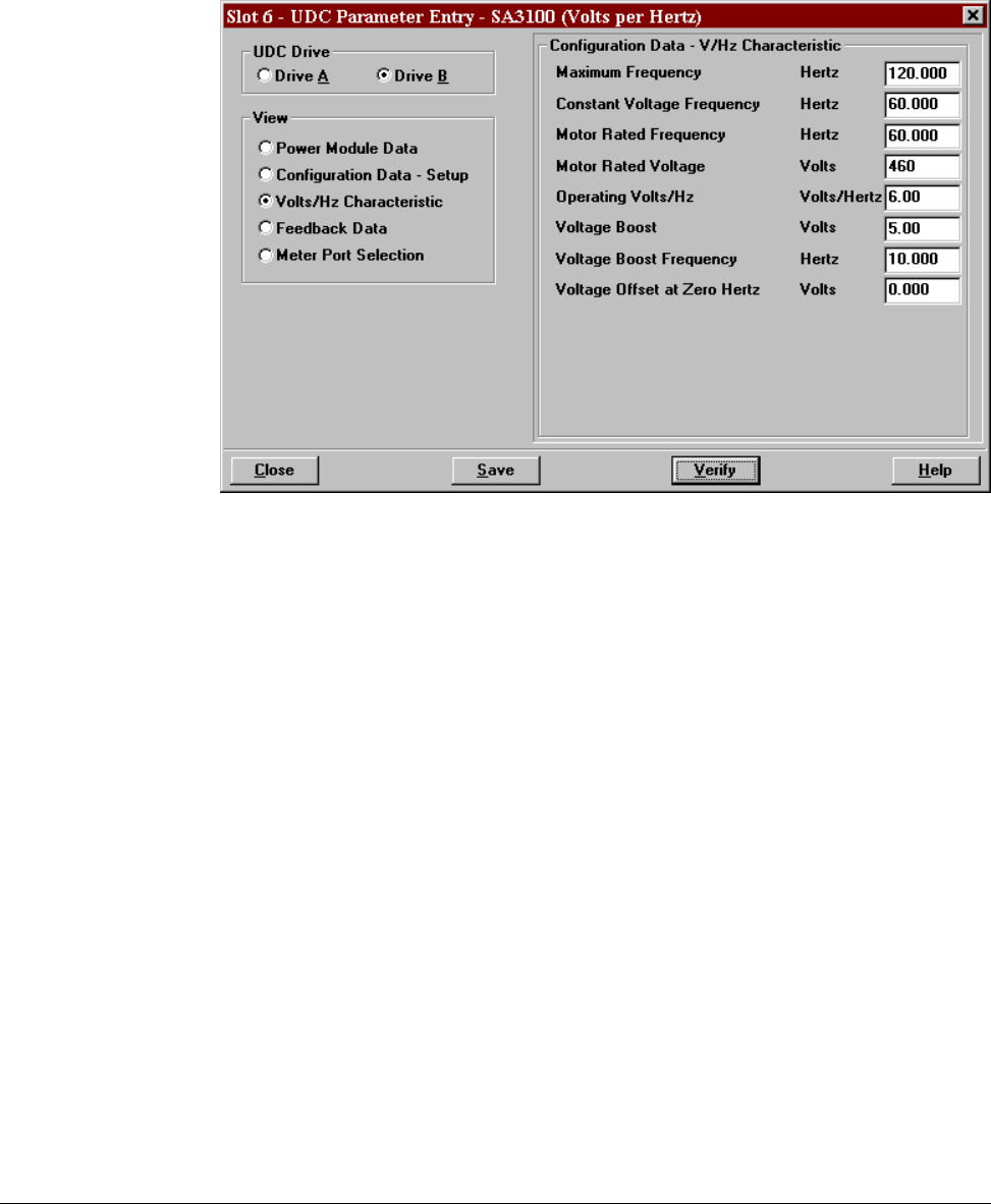
2.4.3 V/Hz Characteristic Screen (Volts per Hertz)
The V/Hz Characteristic parameter screen allows you to enter specific information
about the motor and V/Hz regulator. See figure 2.11.
• Maximum Frequency (Hertz)
Maximum Frequency defines the maximum frequency which will be output from the
drive. Resolution is 0.001 Hz.
• Constant Voltage Frequency (Hertz)
Constant Voltage Frequency is the frequency point on the volts per hertz curve that
marks the beginning of the constant voltage region. The voltage remains constant
for all frequencies at or above the constant frequency point. Resolution is 0.001 Hz.
• Motor Rated Frequency (Hertz)
Motor Rated Frequency is divided into Motor Rated Voltage to define the motor
rated V/Hz excitation. Resolution is 0.001 Hz.
• Motor Rated Voltage (Volts)
Motor Rated Voltage divided by Motor Rated Frequency defines the motor rated
V/Hz excitation. Enter the value in volts.
• Operating Volts/Hz (Volts/Hertz)
The Operating Volts/Hz entry represents the volts per hertz ratio value. The value
entered must be less than or equal to the Motor Rated Voltage divided by the Motor
Rated Frequency. If no value is entered, a default value equal to the Motor Rated
Voltage divided by the Motor Rated Frequency is provided. Resolution is 0.01V/Hz.
Figure 2.11 – V/Hz Characteristic Parameter Entry Screen (Volts per Hertz)