
Instruction Manual
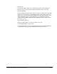
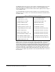
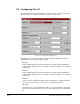

Table Of Contents
- S-3056-1 Distributed Power System SA3100 Drive Configuration and Programming Instruction Manual
- Important User Information
- Contents
- List of Figures
- List of Tables
- Chapter 1 Introduction
- Chapter 2 Configuring the UDC Module, Regulator Type, and Parameters
- 2.1 Adding a Universal Drive Controller (UDC) Module
- 2.2 Entering the Drive Parameters
- 2.3 Configuring the Vector with Constant Power Regulator
- 2.4 Configuring the Volts per Hertz (V/Hz) Regulator
- 2.5 Configuring Flex I/O
- 2.6 Generating Drive Parameter Files and Printing Drive Parameters
- Chapter 3 Configuring the UDC Module’s Registers
- 3.1 Register and Bit Reference Conventions Used in this Manual
- 3.2 Flex I/O Port Registers (Registers 0-23)
- 3.3 UDC/PMI Communication Status Registers (Registers 80-89/1080-1089)
- 3.4 Command Registers (Registers 100-199/1100-1199)
- 3.5 Feedback Registers (Registers 200-299/1200-1299)
- 3.6 Application Registers (Registers 300-599, Every Scan) (Registers 1300-1599, Every Nth Scan)
- 3.7 UDC Module Test I/O Registers (Registers 1000-1017)
- 3.8 Interrupt Status and Control Registers (Registers 2000-2047)
- Chapter 4 Application Programming for DPS Drive Control
- Chapter 5 On-Line Operation
- Appendix A SA3100 Vector Regulator Register Reference
- Appendix B SA3100 Volts / Hertz Regulator Register Reference
- Appendix C SA3100 Local Tunable Variables
- Appendix D Vector with Constant Power Regulator
- Appendix E Volts per Hertz (V/Hz) Regulator
- Appendix F Status of Data in the AutoMax Rack After a STOP_ALL Command or STOP_ALL Fault
- Appendix G Torque Overload Ratio Parameter Precautions
- Appendix H Default Carrier Frequency and Carrier Frequency Limit for Drive Horsepower Ranges
- Appendix I Vector with Constant Power Parameter Entry Example
- Index
Configuring the UDC Module, Regulator Type, and Parameters
2-21
• Voltage Boost Volts (Volts)
Voltage Boost Volts and Voltage Boost Frequency define a point on the V/Hz curve
where the slope changes, typically to accommodate low frequency instability.
Resolution is 0.01V. Voltage Boost Volts is typically used to extend the range at
constant torque to lower frequencies. This can also be used to avoid the “low
frequency instability region” which is found in some motors with low or no
connected inertia and low friction loads. When using the voltage boost with the
variable torque configuration, the voltage value raises or lowers the central portion
of the V/Hz characteristic (see Figure E.3).
• Voltage Boost Frequency (Hertz)
Voltage Boost Frequency and Voltage Boost Volts define a point in the V/Hz curve
where the slope changes, typically to accommodate low frequency instability.
Resolution is 0.001 Hz.
• Voltage Offset at Zero Hertz (Volts)
Voltage Offset at Zero Hertz is the voltage to be added at zero hertz to adjust the
initial point on the volts per hertz curve. Resolution is 0.001V.
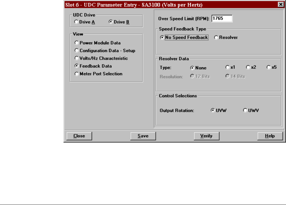
2.4.4 Feedback and Control Data Screen (Volts per Hertz)
No speed feedback is used with the Volts per Hertz regulator. The following Control
Data Parameters can be entered with this screen. See figure 2.12.
Figure 2.12 – Speed Feedback and Control Parameter Entry Screen (Volts per Hertz)