
Instruction Manual
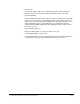
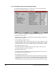
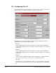
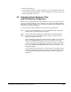

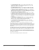
Table Of Contents
- S-3056-1 Distributed Power System SA3100 Drive Configuration and Programming Instruction Manual
- Important User Information
- Contents
- List of Figures
- List of Tables
- Chapter 1 Introduction
- Chapter 2 Configuring the UDC Module, Regulator Type, and Parameters
- 2.1 Adding a Universal Drive Controller (UDC) Module
- 2.2 Entering the Drive Parameters
- 2.3 Configuring the Vector with Constant Power Regulator
- 2.4 Configuring the Volts per Hertz (V/Hz) Regulator
- 2.5 Configuring Flex I/O
- 2.6 Generating Drive Parameter Files and Printing Drive Parameters
- Chapter 3 Configuring the UDC Module’s Registers
- 3.1 Register and Bit Reference Conventions Used in this Manual
- 3.2 Flex I/O Port Registers (Registers 0-23)
- 3.3 UDC/PMI Communication Status Registers (Registers 80-89/1080-1089)
- 3.4 Command Registers (Registers 100-199/1100-1199)
- 3.5 Feedback Registers (Registers 200-299/1200-1299)
- 3.6 Application Registers (Registers 300-599, Every Scan) (Registers 1300-1599, Every Nth Scan)
- 3.7 UDC Module Test I/O Registers (Registers 1000-1017)
- 3.8 Interrupt Status and Control Registers (Registers 2000-2047)
- Chapter 4 Application Programming for DPS Drive Control
- Chapter 5 On-Line Operation
- Appendix A SA3100 Vector Regulator Register Reference
- Appendix B SA3100 Volts / Hertz Regulator Register Reference
- Appendix C SA3100 Local Tunable Variables
- Appendix D Vector with Constant Power Regulator
- Appendix E Volts per Hertz (V/Hz) Regulator
- Appendix F Status of Data in the AutoMax Rack After a STOP_ALL Command or STOP_ALL Fault
- Appendix G Torque Overload Ratio Parameter Precautions
- Appendix H Default Carrier Frequency and Carrier Frequency Limit for Drive Horsepower Ranges
- Appendix I Vector with Constant Power Parameter Entry Example
- Index
2-24
SA3100 Drive Configuration and Programming
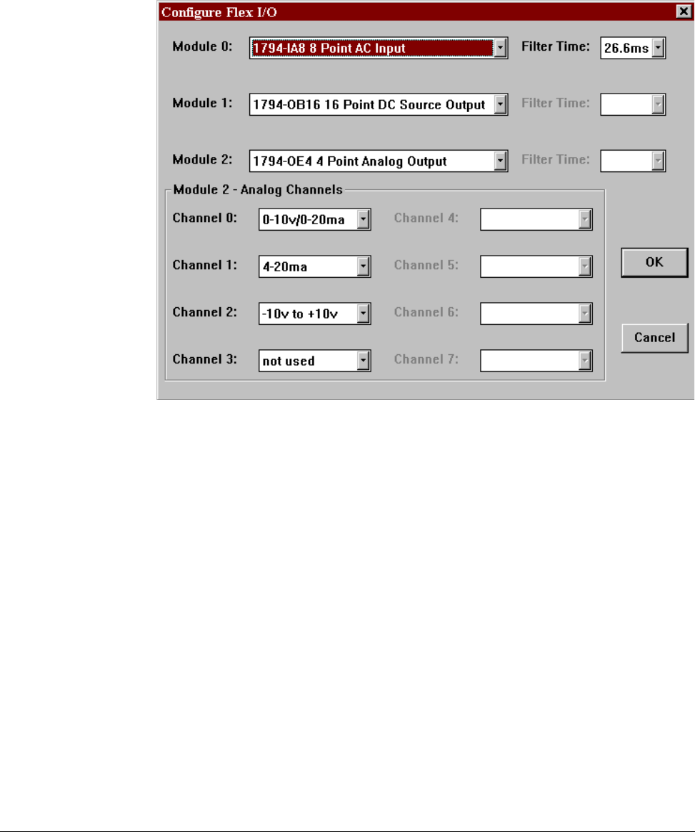
2.5 Configuring Flex I/O
The Configure Flex I/O Parameter Entry Screen allows you to configure your Flex I/O
Modules, if Flex I/O is being used with your system. See figure 2.14.
A maximum of three Flex I/O modules is allowed. Module 0 and Module 1 must be
digital; Module 2 can be either digital or analog.
• Module 0
Select a digital I/O module from the pull-down list. Only the supported digital I/O
modules will be displayed. There is no default selection. You must choose a module
from the list.
• Module 1
Select a digital I/O module from the pull-down list. Only the supported digital I/O
modules will be displayed. There is no default selection. You must choose a module
from the list.
• Module 2
Select an analog or digital I/O module from the pull-down list of supported modules.
There is no default selection. You must choose a module from the list.
• Filter Time
This parameter is used only with input modules. The system determines the default
filter time for the module selected. You may select a different time from a pull-down
list.
Figure 2.14 – Flex I/O Parameter Entry Screen