
Instruction Manual
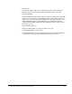
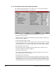
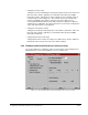
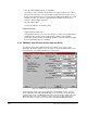
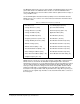
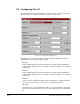
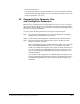

Table Of Contents
- S-3056-1 Distributed Power System SA3100 Drive Configuration and Programming Instruction Manual
- Important User Information
- Contents
- List of Figures
- List of Tables
- Chapter 1 Introduction
- Chapter 2 Configuring the UDC Module, Regulator Type, and Parameters
- 2.1 Adding a Universal Drive Controller (UDC) Module
- 2.2 Entering the Drive Parameters
- 2.3 Configuring the Vector with Constant Power Regulator
- 2.4 Configuring the Volts per Hertz (V/Hz) Regulator
- 2.5 Configuring Flex I/O
- 2.6 Generating Drive Parameter Files and Printing Drive Parameters
- Chapter 3 Configuring the UDC Module’s Registers
- 3.1 Register and Bit Reference Conventions Used in this Manual
- 3.2 Flex I/O Port Registers (Registers 0-23)
- 3.3 UDC/PMI Communication Status Registers (Registers 80-89/1080-1089)
- 3.4 Command Registers (Registers 100-199/1100-1199)
- 3.5 Feedback Registers (Registers 200-299/1200-1299)
- 3.6 Application Registers (Registers 300-599, Every Scan) (Registers 1300-1599, Every Nth Scan)
- 3.7 UDC Module Test I/O Registers (Registers 1000-1017)
- 3.8 Interrupt Status and Control Registers (Registers 2000-2047)
- Chapter 4 Application Programming for DPS Drive Control
- Chapter 5 On-Line Operation
- Appendix A SA3100 Vector Regulator Register Reference
- Appendix B SA3100 Volts / Hertz Regulator Register Reference
- Appendix C SA3100 Local Tunable Variables
- Appendix D Vector with Constant Power Regulator
- Appendix E Volts per Hertz (V/Hz) Regulator
- Appendix F Status of Data in the AutoMax Rack After a STOP_ALL Command or STOP_ALL Fault
- Appendix G Torque Overload Ratio Parameter Precautions
- Appendix H Default Carrier Frequency and Carrier Frequency Limit for Drive Horsepower Ranges
- Appendix I Vector with Constant Power Parameter Entry Example
- Index

Configuring the UDC Module, Regulator Type, and Parameters
2-25
• Channel 0 to Channel 7
If an analog I/O module is selected for Module 2, you must configure the channels
for the analog module appropriately. No error checking is done by the system. The
channels all default to “not used”.
2.6 Generating Drive Parameter Files
and Printing Drive Parameters
When you have completed all of the drive parameter screens, you can select “Close”
to leave the Parameter Entry Screens and return to the master rack diagram with the
UDC module selected. Zoom out or select the Exit command from the Configure menu
to return to the System Configurator.
You can generate the drive parameter files by using the steps that follow.
Step 1. From the System Configurator, access the Task Manager by selecting the
Manage Tasks command from the Rack menu.
Step 2. Select the Generate Configuration command from the Commands menu.
Step 3. Check the Generate Drive Parameter Files option in the Generate Files
dialog box, and then select OK.
A file containing the newly-entered drive parameters will be created. The file
will be named PARAMxx.POB, where xx is the slot number of the UDC
module. Note that the drive parameter files must be loaded to the rack before
(or at the same time as) the UDC application tasks are loaded to the rack.
Refer to the AutoMax Programming Executive instruction manual for more
detailed information.
You can print the drive parameters for a UDC module you specify by using
the Print command from the Rack menu in the System Configurator. Refer to
the AutoMax Programming Executive instruction manual for step-by-step
instructions.