
Instruction Manual
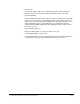
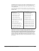
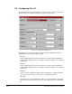

Table Of Contents
- S-3056-1 Distributed Power System SA3100 Drive Configuration and Programming Instruction Manual
- Important User Information
- Contents
- List of Figures
- List of Tables
- Chapter 1 Introduction
- Chapter 2 Configuring the UDC Module, Regulator Type, and Parameters
- 2.1 Adding a Universal Drive Controller (UDC) Module
- 2.2 Entering the Drive Parameters
- 2.3 Configuring the Vector with Constant Power Regulator
- 2.4 Configuring the Volts per Hertz (V/Hz) Regulator
- 2.5 Configuring Flex I/O
- 2.6 Generating Drive Parameter Files and Printing Drive Parameters
- Chapter 3 Configuring the UDC Module’s Registers
- 3.1 Register and Bit Reference Conventions Used in this Manual
- 3.2 Flex I/O Port Registers (Registers 0-23)
- 3.3 UDC/PMI Communication Status Registers (Registers 80-89/1080-1089)
- 3.4 Command Registers (Registers 100-199/1100-1199)
- 3.5 Feedback Registers (Registers 200-299/1200-1299)
- 3.6 Application Registers (Registers 300-599, Every Scan) (Registers 1300-1599, Every Nth Scan)
- 3.7 UDC Module Test I/O Registers (Registers 1000-1017)
- 3.8 Interrupt Status and Control Registers (Registers 2000-2047)
- Chapter 4 Application Programming for DPS Drive Control
- Chapter 5 On-Line Operation
- Appendix A SA3100 Vector Regulator Register Reference
- Appendix B SA3100 Volts / Hertz Regulator Register Reference
- Appendix C SA3100 Local Tunable Variables
- Appendix D Vector with Constant Power Regulator
- Appendix E Volts per Hertz (V/Hz) Regulator
- Appendix F Status of Data in the AutoMax Rack After a STOP_ALL Command or STOP_ALL Fault
- Appendix G Torque Overload Ratio Parameter Precautions
- Appendix H Default Carrier Frequency and Carrier Frequency Limit for Drive Horsepower Ranges
- Appendix I Vector with Constant Power Parameter Entry Example
- Index
Configuring the UDC Module’s Registers
3-1
CHAPTER 3
Configuring the UDC Module’s
Registers
The Variable Configurator application in the AutoMax Programming Executive is used
to assign common variable names to the dual port memory registers on the UDC
module. You can access these variable names by declaring them using the BASIC
statement COMMON. The dual port memory has 2048 16-bit registers that are
available to the AutoMax Processor and to the tasks that run on the UDC module.
The drive A and drive B registers that are assigned variable names will be latched into
internal memory at the beginning of every scan of the UDC task to provide for a
consistent context for evaluation. The UDC tasks (A and B) may be started and
stopped independently of each other. At the end of the scan, the variables that have
changed will be written back to the dual port memory.
Note that the dual port memory on the UDC module is treated like I/O data in terms of
how the data is affected by Stop All commands and power cycling.
You can access the Variable Configurator by selecting Configure Variables from the
Configure menu in the Rack Configurator. Refer to the AutoMax Programming
Executive instruction manual for the procedures used to configure variables.
The sections that follow describe the registers you can configure in each view:
• The Port 0 Flex I/O Rail view is used to configure the registers assigned to the
hardware that is attached to the PMI Flex I/O port. (These registers can also be
accessed by double-clicking the PMI view.)
!
ATTENTION:Only qualified electrical personnel familiar with the
construction and operation of this equipment and the hazards involved
should install, adjust, operate, or service this equipment. Read and
understand this manual and other applicable manuals in their entirety
before proceeding. Failure to observe this precaution could result in
severe bodily injury or loss of life.
ATTENTION:Only qualified Drive Systems personnel or other trained
personnel who understand the potential hazards involved may make
modifications to the variable configuration. Any modifications may result
in uncontrolled machine operation. Failure to observe this precaution
could result in damage to equipment and bodily injury.
ATTENTION:Registers and bits in the UDC module that are described
as “read only” or for “system use only” must not be written to by the user.
Writing to these registers and bits may result in improper system
operation. Failure to observe this precaution could result in bodily injury.