
Instruction Manual
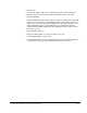
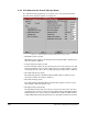
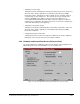
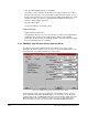
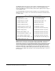
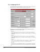

Table Of Contents
- S-3056-1 Distributed Power System SA3100 Drive Configuration and Programming Instruction Manual
- Important User Information
- Contents
- List of Figures
- List of Tables
- Chapter 1 Introduction
- Chapter 2 Configuring the UDC Module, Regulator Type, and Parameters
- 2.1 Adding a Universal Drive Controller (UDC) Module
- 2.2 Entering the Drive Parameters
- 2.3 Configuring the Vector with Constant Power Regulator
- 2.4 Configuring the Volts per Hertz (V/Hz) Regulator
- 2.5 Configuring Flex I/O
- 2.6 Generating Drive Parameter Files and Printing Drive Parameters
- Chapter 3 Configuring the UDC Module’s Registers
- 3.1 Register and Bit Reference Conventions Used in this Manual
- 3.2 Flex I/O Port Registers (Registers 0-23)
- 3.3 UDC/PMI Communication Status Registers (Registers 80-89/1080-1089)
- 3.4 Command Registers (Registers 100-199/1100-1199)
- 3.5 Feedback Registers (Registers 200-299/1200-1299)
- 3.6 Application Registers (Registers 300-599, Every Scan) (Registers 1300-1599, Every Nth Scan)
- 3.7 UDC Module Test I/O Registers (Registers 1000-1017)
- 3.8 Interrupt Status and Control Registers (Registers 2000-2047)
- Chapter 4 Application Programming for DPS Drive Control
- Chapter 5 On-Line Operation
- Appendix A SA3100 Vector Regulator Register Reference
- Appendix B SA3100 Volts / Hertz Regulator Register Reference
- Appendix C SA3100 Local Tunable Variables
- Appendix D Vector with Constant Power Regulator
- Appendix E Volts per Hertz (V/Hz) Regulator
- Appendix F Status of Data in the AutoMax Rack After a STOP_ALL Command or STOP_ALL Fault
- Appendix G Torque Overload Ratio Parameter Precautions
- Appendix H Default Carrier Frequency and Carrier Frequency Limit for Drive Horsepower Ranges
- Appendix I Vector with Constant Power Parameter Entry Example
- Index

3-2
SA3100 Drive Configuration and Programming
• The Command Registers view is used to configure pre-defined drive control
registers that are written to either by an AutoMax application task or by a UDC
application task and then sent to the PMI.
• The Feedback Registers view is used to configure the feedback registers that
display the current status of the drive. These registers are written to by the PMI.
• The Application Registers Updated Every Scan view is used to configure the
application registers that are used for the passing of application-specific control and
status data between an AutoMax Processor and the UDC module on every scan.
This register range is shared by drive A and drive B.
• The Application Registers Updated Every Nth Scan view is used to configure
the application registers that are used for the passing of application-specific control
and status data between an AutoMax Processor and the UDC module on every Nth
scan, where “N” is defined in register 2001. This register range is shared by drive A
and drive B.
• The UDC Module Test I/O Register view is used to configure the register that
displays the status of the UDC module’s test switches and LED indicators. This
view is also used to configure the UDC module’s D/A meter ports.
• The Interrupt Status and Control Registers view is used to configure the
registers that control a user-defined interrupt to an AutoMax task and enable the
CCLK signal on the backplane.
The Gain Data values that are used by the PMI are NOT mapped to the UDC
module’s dual port registers. The gain values are held in local tunables with reserved
names which must be defined in the UDC task for the drive (A or B). The programmer
must use the pre-assigned local tunable reserved names described in Appendix B of
this manual.
Note that register values are generally in the appropriate engineering units and that
the variable names provided here are suggestions only; your variable names may be
different. Duplicate common variable names are not permitted within any one rack.
Table 3.1 lists the configuration views in the AutoMax Programming Executive, the
registers to be configured in each, and the section of this instruction manual in which
the registers are discussed.
Table 3.2 lists the UDC dual port registers in numerical order.