
Instruction Manual
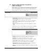
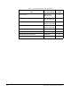
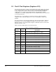
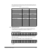
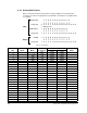
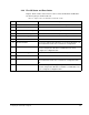
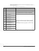
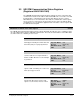
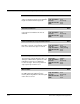
Table Of Contents
- S-3056-1 Distributed Power System SA3100 Drive Configuration and Programming Instruction Manual
- Important User Information
- Contents
- List of Figures
- List of Tables
- Chapter 1 Introduction
- Chapter 2 Configuring the UDC Module, Regulator Type, and Parameters
- 2.1 Adding a Universal Drive Controller (UDC) Module
- 2.2 Entering the Drive Parameters
- 2.3 Configuring the Vector with Constant Power Regulator
- 2.4 Configuring the Volts per Hertz (V/Hz) Regulator
- 2.5 Configuring Flex I/O
- 2.6 Generating Drive Parameter Files and Printing Drive Parameters
- Chapter 3 Configuring the UDC Module’s Registers
- 3.1 Register and Bit Reference Conventions Used in this Manual
- 3.2 Flex I/O Port Registers (Registers 0-23)
- 3.3 UDC/PMI Communication Status Registers (Registers 80-89/1080-1089)
- 3.4 Command Registers (Registers 100-199/1100-1199)
- 3.5 Feedback Registers (Registers 200-299/1200-1299)
- 3.6 Application Registers (Registers 300-599, Every Scan) (Registers 1300-1599, Every Nth Scan)
- 3.7 UDC Module Test I/O Registers (Registers 1000-1017)
- 3.8 Interrupt Status and Control Registers (Registers 2000-2047)
- Chapter 4 Application Programming for DPS Drive Control
- Chapter 5 On-Line Operation
- Appendix A SA3100 Vector Regulator Register Reference
- Appendix B SA3100 Volts / Hertz Regulator Register Reference
- Appendix C SA3100 Local Tunable Variables
- Appendix D Vector with Constant Power Regulator
- Appendix E Volts per Hertz (V/Hz) Regulator
- Appendix F Status of Data in the AutoMax Rack After a STOP_ALL Command or STOP_ALL Fault
- Appendix G Torque Overload Ratio Parameter Precautions
- Appendix H Default Carrier Frequency and Carrier Frequency Limit for Drive Horsepower Ranges
- Appendix I Vector with Constant Power Parameter Entry Example
- Index

Configuring the UDC Module’s Registers
3-3
3.1 Register and Bit Reference Conventions
Used in this Manual
Register numbers are shown using the convention A/B, where A is the drive A register
number and B is the drive B register number. Note that the Interrupt Status Control
registers and the Application registers are the same for both drive A and drive B.
Register descriptions are shown in the following format:
• Register Name: Functional name of the register (e.g., Torque Reference Register).
• Register Numbers: Memory addresses of registers A and B.
• Sug. Var. Name: Suggested variable name for the register (e.g., TRQ_REF%).
• Units: Scaling unit applied to the value stored in the register (e.g., counts,
amps
*10, etc.).
• Range: The upper and lower limits of the value, where applicable (e.g. -4095 to
+4095).
• Access: The level of access by the application task (Read, Write, or Read/Write).
Throughout this manual, bit descriptions are shown in the following format:
• Bit Name: Functional name of the bit (e.g., DC Bus Over Voltage Fault).
• Bit Number: The specific bit location within the register (e.g., Bit 0).
• Hex Value: The position within the 16 bit register (e.g., Bit Number 4 = 0010H)
• Sug. Var. Name: Suggested variable name for this bit (e.g., FLT_OV@ ).
• Access: The level of access by the application task (e.g., Read/Write).
• UDC Error Code: A drive fault’s corresponding error code (e.g. 1018). This is
reported in the log for the task in which the error occurred.
• LED: The corresponding status LED, where applicable (e.g., EXT FLT on the PMI
Regulator).
Register Name Register Numbers
[Functional description] Sug. Var. Name:
Units:
Range:
Access:
[Additional descriptive details, if required]
Bit Name Bit Number
[Functional description]
Hex Value:
Sug. Var. Name:
Access:
UDC Error Code:
LED:
[Additional descriptive details, if required]