
Instruction Manual
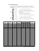
Table Of Contents
- S-3056-1 Distributed Power System SA3100 Drive Configuration and Programming Instruction Manual
- Important User Information
- Contents
- List of Figures
- List of Tables
- Chapter 1 Introduction
- Chapter 2 Configuring the UDC Module, Regulator Type, and Parameters
- 2.1 Adding a Universal Drive Controller (UDC) Module
- 2.2 Entering the Drive Parameters
- 2.3 Configuring the Vector with Constant Power Regulator
- 2.4 Configuring the Volts per Hertz (V/Hz) Regulator
- 2.5 Configuring Flex I/O
- 2.6 Generating Drive Parameter Files and Printing Drive Parameters
- Chapter 3 Configuring the UDC Module’s Registers
- 3.1 Register and Bit Reference Conventions Used in this Manual
- 3.2 Flex I/O Port Registers (Registers 0-23)
- 3.3 UDC/PMI Communication Status Registers (Registers 80-89/1080-1089)
- 3.4 Command Registers (Registers 100-199/1100-1199)
- 3.5 Feedback Registers (Registers 200-299/1200-1299)
- 3.6 Application Registers (Registers 300-599, Every Scan) (Registers 1300-1599, Every Nth Scan)
- 3.7 UDC Module Test I/O Registers (Registers 1000-1017)
- 3.8 Interrupt Status and Control Registers (Registers 2000-2047)
- Chapter 4 Application Programming for DPS Drive Control
- Chapter 5 On-Line Operation
- Appendix A SA3100 Vector Regulator Register Reference
- Appendix B SA3100 Volts / Hertz Regulator Register Reference
- Appendix C SA3100 Local Tunable Variables
- Appendix D Vector with Constant Power Regulator
- Appendix E Volts per Hertz (V/Hz) Regulator
- Appendix F Status of Data in the AutoMax Rack After a STOP_ALL Command or STOP_ALL Fault
- Appendix G Torque Overload Ratio Parameter Precautions
- Appendix H Default Carrier Frequency and Carrier Frequency Limit for Drive Horsepower Ranges
- Appendix I Vector with Constant Power Parameter Entry Example
- Index
3-6
SA3100 Drive Configuration and Programming
3.2 Flex I/O Port Registers (Registers 0-23)
The Flex I/O Port 0 view is used to assign variable names and configure the registers
used for the Flex I/O port on the PMI. If you have no hardware attached to this port,
do not configure these registers. All of the Flex I/O data for PMI A and PMI B is
combined into one section of the dual port memory. The appropriate variable
configuration screen will be displayed based on the hardware that you have specified
is connected to the port.
Note that the use of each register is a function of the type of Flex I/O module
configured. After a Stop All, outputs are reset to zero and inputs continue to be
updated.
The Flex I/O interface is designed to handle up to three Flex I/O modules. Registers
0/12 and 1/13 are reserved for digital I/O. Registers 2/14 to 9/21 can be used for a
digital I/O module or an analog module. Registers 10/22 and 11/23 are used for Flex
I/O status and error codes.
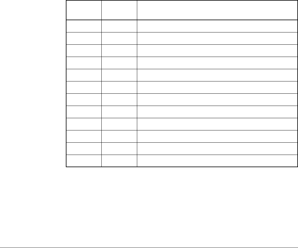
Table 3.3 lists the UDC registers reserved for Flex I/O.
Table 3.3 – Flex I/O Reserved Registers
Drive A
Registers
Drive B
Registers Description
0 12 Flex I/O Module 0, Digital (input or output)
1 13 Flex I/O Module 1, Digital (input or output)
2 14 Flex I/O Module 2, Digital or Analog 0 (input or output)
3 15 Flex I/O Module 2, Analog 1 (input or output)
4 16 Flex I/O Module 2, Analog 2 (input or output)
5 17 Flex I/O Module 2, Analog 3 (input or output)
6 18 Flex I/O Module 2, Analog 4 (input or output)
7 19 Flex I/O Module 2, Analog 5 (input or output)
8 20 Flex I/O Module 2, Analog 6 (input)
9 21 Flex I/O Module 2, Analog 7 (input)
10 22 Flex System Faults, Modules 0 and 1 faults
11 23 Flex I/O Module 2 faults