
Instruction Manual
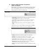
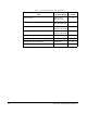
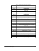
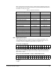
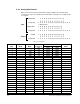
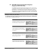
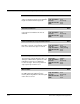
Table Of Contents
- S-3056-1 Distributed Power System SA3100 Drive Configuration and Programming Instruction Manual
- Important User Information
- Contents
- List of Figures
- List of Tables
- Chapter 1 Introduction
- Chapter 2 Configuring the UDC Module, Regulator Type, and Parameters
- 2.1 Adding a Universal Drive Controller (UDC) Module
- 2.2 Entering the Drive Parameters
- 2.3 Configuring the Vector with Constant Power Regulator
- 2.4 Configuring the Volts per Hertz (V/Hz) Regulator
- 2.5 Configuring Flex I/O
- 2.6 Generating Drive Parameter Files and Printing Drive Parameters
- Chapter 3 Configuring the UDC Module’s Registers
- 3.1 Register and Bit Reference Conventions Used in this Manual
- 3.2 Flex I/O Port Registers (Registers 0-23)
- 3.3 UDC/PMI Communication Status Registers (Registers 80-89/1080-1089)
- 3.4 Command Registers (Registers 100-199/1100-1199)
- 3.5 Feedback Registers (Registers 200-299/1200-1299)
- 3.6 Application Registers (Registers 300-599, Every Scan) (Registers 1300-1599, Every Nth Scan)
- 3.7 UDC Module Test I/O Registers (Registers 1000-1017)
- 3.8 Interrupt Status and Control Registers (Registers 2000-2047)
- Chapter 4 Application Programming for DPS Drive Control
- Chapter 5 On-Line Operation
- Appendix A SA3100 Vector Regulator Register Reference
- Appendix B SA3100 Volts / Hertz Regulator Register Reference
- Appendix C SA3100 Local Tunable Variables
- Appendix D Vector with Constant Power Regulator
- Appendix E Volts per Hertz (V/Hz) Regulator
- Appendix F Status of Data in the AutoMax Rack After a STOP_ALL Command or STOP_ALL Fault
- Appendix G Torque Overload Ratio Parameter Precautions
- Appendix H Default Carrier Frequency and Carrier Frequency Limit for Drive Horsepower Ranges
- Appendix I Vector with Constant Power Parameter Entry Example
- Index
Configuring the UDC Module’s Registers
3-7
Table 3.4 lists the Flex I/O modules that are supported by the SA3100 system. Refer
to the appropriate Flex I/O instruction manuals for specific information about the Flex
I/O modules used in your system.
3.2.1 Digital Data Formats
Some digital I/O modules are only 8 bits and do not require the full 16 bits of the
assigned UDC register. If the module is only 8 bits, then bits 8 through 15 are not
used. Bit 0 is defined as Digital I/O channel 0, bit 1 is channel 1, etc.
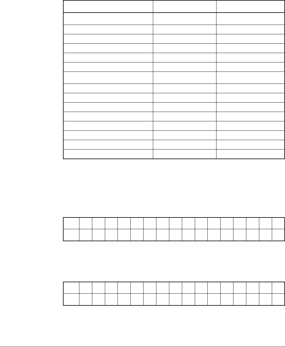
Flex I/O module IB10X0B6 (10 input/6 output digital combo module) is mapped to
UDC memory as shown below, with the lower ten bits configured as inputs and the
upper 6 bits as outputs.
0 = Output
I = Input
Table 3.4 – Supported Flex I/O Modules
Module Type
Catalogue Number Publication Number
Digital 24V DC
16 Point DC Sink Input 1794-IB16 1794-5.4
16 Point DC Source Output 1794-OB16 1794-2.3
16 Point DC Source Input 1794-IV16 1794-5.28
16 Point DC Sink Output 1794-OV16 1794-5.29
10 Input / 6 Output DC Combo 1794-IB10XOB6 1794-5.24
Digital 120V AC
8 Point AC Input 1794-IA8 1794-5.9
8 Point AC Output 1794-OA8 1794-5.10
Analog
8 Point Analog Input 1794-IE8/B 1794-5.6
4 Point Analog Output 1794-OE4/B 1794-5.5
4 Input / 2 Output Analog 1794-IE4XOE2/B 1794-5.15
Relay
8 Point Relay Output 1794-OW8 1794-5.19
Data Format: 8-bit Digital I/O
Bit 1514131211109876543210
Data --------I/OI/OI/OI/OI/OI/OI/OI/O
Data Format: Module IB10X0B6 - 10 Input / 6 Output Digital Combo
Bit 1514131211109876543210
Data OOOOOOIIIIIIIIII