
Instruction Manual
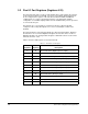
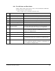
Table Of Contents
- S-3056-1 Distributed Power System SA3100 Drive Configuration and Programming Instruction Manual
- Important User Information
- Contents
- List of Figures
- List of Tables
- Chapter 1 Introduction
- Chapter 2 Configuring the UDC Module, Regulator Type, and Parameters
- 2.1 Adding a Universal Drive Controller (UDC) Module
- 2.2 Entering the Drive Parameters
- 2.3 Configuring the Vector with Constant Power Regulator
- 2.4 Configuring the Volts per Hertz (V/Hz) Regulator
- 2.5 Configuring Flex I/O
- 2.6 Generating Drive Parameter Files and Printing Drive Parameters
- Chapter 3 Configuring the UDC Module’s Registers
- 3.1 Register and Bit Reference Conventions Used in this Manual
- 3.2 Flex I/O Port Registers (Registers 0-23)
- 3.3 UDC/PMI Communication Status Registers (Registers 80-89/1080-1089)
- 3.4 Command Registers (Registers 100-199/1100-1199)
- 3.5 Feedback Registers (Registers 200-299/1200-1299)
- 3.6 Application Registers (Registers 300-599, Every Scan) (Registers 1300-1599, Every Nth Scan)
- 3.7 UDC Module Test I/O Registers (Registers 1000-1017)
- 3.8 Interrupt Status and Control Registers (Registers 2000-2047)
- Chapter 4 Application Programming for DPS Drive Control
- Chapter 5 On-Line Operation
- Appendix A SA3100 Vector Regulator Register Reference
- Appendix B SA3100 Volts / Hertz Regulator Register Reference
- Appendix C SA3100 Local Tunable Variables
- Appendix D Vector with Constant Power Regulator
- Appendix E Volts per Hertz (V/Hz) Regulator
- Appendix F Status of Data in the AutoMax Rack After a STOP_ALL Command or STOP_ALL Fault
- Appendix G Torque Overload Ratio Parameter Precautions
- Appendix H Default Carrier Frequency and Carrier Frequency Limit for Drive Horsepower Ranges
- Appendix I Vector with Constant Power Parameter Entry Example
- Index
3-10
SA3100 Drive Configuration and Programming
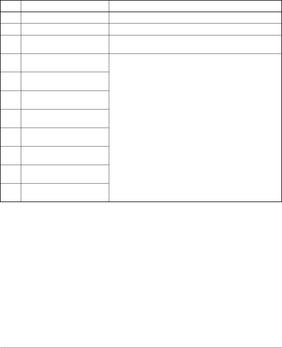
Register 11/23 contains status and error codes for Flex I/O Module 2. The memory
map is shown in table 3.7.
Table 3.7 – Register 11/23 - Flex I/O Module 2 Faults
Bit Name Description
0 Module 2 Not Plugged In Set if no device is detected at Module 2 port.
1 Module 2 Communication Error Set if there is a serial communication error with Module 2.
2 Module 2 Bad ID Set if a non-supported module ID is received from Module 2 or if
the module ID received does not match the configured ID.
8 Channel 0 - Open Output/
Underrange Input
Bits 8 to 15 are set if there is an open output (4 - 20 mA current
output only) or an under range input (4 - 20 mA current input
only).
If a digital input is installed for Module 2 these bits are not used.
9 Channel 1 - Open Output/
Underrange Input
10 Channel 2 - Open Output/
Underrange Input
11 Channel 3 - Open Output/
Underrange Input
12 Channel 4 - Open Output/
Underrange Input
13 Channel 5 - Open Output/
Underrange Input
14 Channel 6 - Open Output/
Underrange Input
15 Channel 7 - Open Output/
Underrange Input