
Instruction Manual
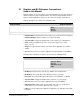
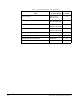
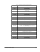
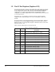
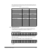
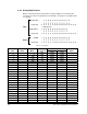
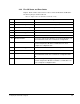
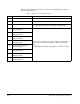
Table Of Contents
- S-3056-1 Distributed Power System SA3100 Drive Configuration and Programming Instruction Manual
- Important User Information
- Contents
- List of Figures
- List of Tables
- Chapter 1 Introduction
- Chapter 2 Configuring the UDC Module, Regulator Type, and Parameters
- 2.1 Adding a Universal Drive Controller (UDC) Module
- 2.2 Entering the Drive Parameters
- 2.3 Configuring the Vector with Constant Power Regulator
- 2.4 Configuring the Volts per Hertz (V/Hz) Regulator
- 2.5 Configuring Flex I/O
- 2.6 Generating Drive Parameter Files and Printing Drive Parameters
- Chapter 3 Configuring the UDC Module’s Registers
- 3.1 Register and Bit Reference Conventions Used in this Manual
- 3.2 Flex I/O Port Registers (Registers 0-23)
- 3.3 UDC/PMI Communication Status Registers (Registers 80-89/1080-1089)
- 3.4 Command Registers (Registers 100-199/1100-1199)
- 3.5 Feedback Registers (Registers 200-299/1200-1299)
- 3.6 Application Registers (Registers 300-599, Every Scan) (Registers 1300-1599, Every Nth Scan)
- 3.7 UDC Module Test I/O Registers (Registers 1000-1017)
- 3.8 Interrupt Status and Control Registers (Registers 2000-2047)
- Chapter 4 Application Programming for DPS Drive Control
- Chapter 5 On-Line Operation
- Appendix A SA3100 Vector Regulator Register Reference
- Appendix B SA3100 Volts / Hertz Regulator Register Reference
- Appendix C SA3100 Local Tunable Variables
- Appendix D Vector with Constant Power Regulator
- Appendix E Volts per Hertz (V/Hz) Regulator
- Appendix F Status of Data in the AutoMax Rack After a STOP_ALL Command or STOP_ALL Fault
- Appendix G Torque Overload Ratio Parameter Precautions
- Appendix H Default Carrier Frequency and Carrier Frequency Limit for Drive Horsepower Ranges
- Appendix I Vector with Constant Power Parameter Entry Example
- Index
3-12
SA3100 Drive Configuration and Programming
UDC Module Communication Status Register (Continued) 80/1080
DMA Format Error Bit 4
The DMA Format Error bit is set if the length
of the received message does not match the
length encoded in the message itself.
Hex Value: 0010H
Sug. Var. Name: N/A
Access: Read only
UDC Error Code: N/A
LED: N/A
Transmitter Underrun Bit 5
The Transmitter Underrun bit is set if the
USC reports a transmit first-in, first-out
underrun.
Hex Value: 0020H
Sug. Var. Name: N/A
Access: Read only
UDC Error Code: N/A
LED: N/A
CCLK Communication Synchronization Error Bit 6
The CCLK Communication Synchronization
Error bit is set if two or more CCLK counter
ticks occur and no message is received.
Hex Value: 0040H
Sug. Var. Name: N/A
Access: Read only
Sug. Var. Name: VDC_RUN@
UDC Error Code: N/A
LED: N/A
External Loopback Data Error Bit 7
The External Loopback Data Error bit is set
during the UDC module loopback test if the
transmit message does not match the
receive message. This test is performed
only at power up or after a reset.
Hex Value: 0080H
Sug. Var. Name: N/A
Access: Read only
UDC Error Code: N/A
LED: N/A
Missed Gains Bit 8
The Missed Gains bit is set if gain data from
the PMI could not be written because
memory was being written to when the gain
values were received.
Hex Value: 0100H
Sug. Var. Name: N/A
Access: Read only
UDC Error Code: N/A
LED: N/A