
Instruction Manual
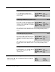
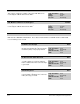
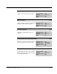
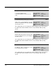

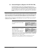

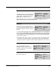
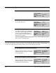
Table Of Contents
- S-3056-1 Distributed Power System SA3100 Drive Configuration and Programming Instruction Manual
- Important User Information
- Contents
- List of Figures
- List of Tables
- Chapter 1 Introduction
- Chapter 2 Configuring the UDC Module, Regulator Type, and Parameters
- 2.1 Adding a Universal Drive Controller (UDC) Module
- 2.2 Entering the Drive Parameters
- 2.3 Configuring the Vector with Constant Power Regulator
- 2.4 Configuring the Volts per Hertz (V/Hz) Regulator
- 2.5 Configuring Flex I/O
- 2.6 Generating Drive Parameter Files and Printing Drive Parameters
- Chapter 3 Configuring the UDC Module’s Registers
- 3.1 Register and Bit Reference Conventions Used in this Manual
- 3.2 Flex I/O Port Registers (Registers 0-23)
- 3.3 UDC/PMI Communication Status Registers (Registers 80-89/1080-1089)
- 3.4 Command Registers (Registers 100-199/1100-1199)
- 3.5 Feedback Registers (Registers 200-299/1200-1299)
- 3.6 Application Registers (Registers 300-599, Every Scan) (Registers 1300-1599, Every Nth Scan)
- 3.7 UDC Module Test I/O Registers (Registers 1000-1017)
- 3.8 Interrupt Status and Control Registers (Registers 2000-2047)
- Chapter 4 Application Programming for DPS Drive Control
- Chapter 5 On-Line Operation
- Appendix A SA3100 Vector Regulator Register Reference
- Appendix B SA3100 Volts / Hertz Regulator Register Reference
- Appendix C SA3100 Local Tunable Variables
- Appendix D Vector with Constant Power Regulator
- Appendix E Volts per Hertz (V/Hz) Regulator
- Appendix F Status of Data in the AutoMax Rack After a STOP_ALL Command or STOP_ALL Fault
- Appendix G Torque Overload Ratio Parameter Precautions
- Appendix H Default Carrier Frequency and Carrier Frequency Limit for Drive Horsepower Ranges
- Appendix I Vector with Constant Power Parameter Entry Example
- Index
3-16
SA3100 Drive Configuration and Programming
PMI Communication Status Register (Continued) 84/1084
Multiplexed Data Verification Failure Bit 9
The Multiplexed Data Verification Failure bit
is set if data multiplexed into
command/feedback messages does not
verify.
Hex Value: 0200H
Sug. Var. Name: N/A
Access: Read only
UDC Error Code: N/A
LED: N/A
Invalid PMI Start Operating System Address Bit 12
The Invalid PMI Start Operating System
Address bit is set by the PMI if the operating
system is not within the allocated operating
system address area.
Hex Value: 1000H
Sug. Var. Name: N/A
Access: Read only
UDC Error Code: N/A
LED: N/A
This condition will cause the loading of the PMI operating system to fail. However,
the UDC module and the PMI will continue to retry loading the PMI operating
system.
Insufficient PMI Memory to Load the PMI Operating System Bit 13
The Insufficient PMI Memory to Load the
PMI Operating System bit is set by the PMI
if there is insufficient memory for loading the
operating system.
Hex Value: 2000H
Sug. Var. Name: N/A
Access: Read only
UDC Error Code: N/A
LED: N/A
This condition will cause the loading of the PMI operating system to fail. However,
the UDC module and the PMI will continue to retry loading the PMI operating
system.
Invalid PMI Load Address Bit 14
The Invalid PMI Load Address bit is set by
the PMI if the address at which it is to load
the operating system is invalid.
Hex Value: 4000H
Sug. Var. Name: N/A
Access: Read only
UDC Error Code: N/A
LED: N/A
This condition will cause the loading of the PMI operating system to fail. However,
the UDC module and the PMI will continue to retry loading the PMI operating
system.