
Instruction Manual
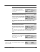
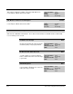

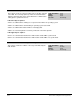
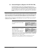

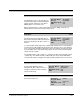
Table Of Contents
- S-3056-1 Distributed Power System SA3100 Drive Configuration and Programming Instruction Manual
- Important User Information
- Contents
- List of Figures
- List of Tables
- Chapter 1 Introduction
- Chapter 2 Configuring the UDC Module, Regulator Type, and Parameters
- 2.1 Adding a Universal Drive Controller (UDC) Module
- 2.2 Entering the Drive Parameters
- 2.3 Configuring the Vector with Constant Power Regulator
- 2.4 Configuring the Volts per Hertz (V/Hz) Regulator
- 2.5 Configuring Flex I/O
- 2.6 Generating Drive Parameter Files and Printing Drive Parameters
- Chapter 3 Configuring the UDC Module’s Registers
- 3.1 Register and Bit Reference Conventions Used in this Manual
- 3.2 Flex I/O Port Registers (Registers 0-23)
- 3.3 UDC/PMI Communication Status Registers (Registers 80-89/1080-1089)
- 3.4 Command Registers (Registers 100-199/1100-1199)
- 3.5 Feedback Registers (Registers 200-299/1200-1299)
- 3.6 Application Registers (Registers 300-599, Every Scan) (Registers 1300-1599, Every Nth Scan)
- 3.7 UDC Module Test I/O Registers (Registers 1000-1017)
- 3.8 Interrupt Status and Control Registers (Registers 2000-2047)
- Chapter 4 Application Programming for DPS Drive Control
- Chapter 5 On-Line Operation
- Appendix A SA3100 Vector Regulator Register Reference
- Appendix B SA3100 Volts / Hertz Regulator Register Reference
- Appendix C SA3100 Local Tunable Variables
- Appendix D Vector with Constant Power Regulator
- Appendix E Volts per Hertz (V/Hz) Regulator
- Appendix F Status of Data in the AutoMax Rack After a STOP_ALL Command or STOP_ALL Fault
- Appendix G Torque Overload Ratio Parameter Precautions
- Appendix H Default Carrier Frequency and Carrier Frequency Limit for Drive Horsepower Ranges
- Appendix I Vector with Constant Power Parameter Entry Example
- Index

Configuring the UDC Module’s Registers
3-19
3.4 Command Registers (Registers 100-199/1100-1199)
The Command Registers view is used to configure command registers. These
registers are used for command data sent to the PMI by the UDC module at the end of
every scan of the UDC Processor. Note that the bits in these registers (except bit 15 in
register 100/1100) are used to command action only and do not indicate the status of
the action commanded. The feedback registers (registers 200/1200 to 299/1299) are
provided for this purpose. The status of the command registers is not retained after a
Stop All.
.
Drive Control Register 100/1100
The Drive Control Register contains the bits that control the operation of the drive. The SA3100 drive can op-
erate in one of four modes: idle, minor loop run, PMI tuning, or bridge test. The default operating mode is idle.
The other three modes are selected using the Drive Control register. Each of these modes is described in de-
tail in the SA3100 Diagnostics, Troubleshooting, and Start-Up Guidelines instruction manual (S-3059).
All bits in this register (except bit 15) can only be written to by a task on an AutoMax Processor. They cannot
be written to by a task on a UDC module. All read/write bits in this register are edge-sensitive and must be
maintained to assert the command.
Enable PMI Run Bit 0
The Enable PMI Run bit is set to enable the
motor regulation minor loop in the PMI
Regulator.
Hex Value: 0001H
Sug. Var. Name: PMI_RUN@
Access: Read/Write
UDC Error Code: N/A
LED: N/A
Enable Tuning Bit 1
The Enable Tuning bit is set to begin the
Auto-Tune procedure.
When the PMI Regulator completes this
task, it sets bit 1 in register 200/1200.
Hex Value: 0002H
Sug. Var. Name: PMI_TUN@
Access: Read/Write
UDC Error Code: N/A
LED: N/A
Setting this bit requests the PMI Regulator to calculate the values for local tunables
STATOR_R_E4% (stator resistance), STATOR_T_E4% (stator time constant), and
STATOR_IZ_E1% (no load stator current).
In Volts per Hertz mode, setting this bit enables the V/Hz inverter to reset the
tunable gains used for generating the V/Hz curve to their default values.