
Instruction Manual
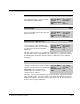
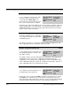
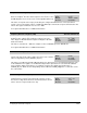
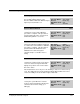
Table Of Contents
- S-3056-1 Distributed Power System SA3100 Drive Configuration and Programming Instruction Manual
- Important User Information
- Contents
- List of Figures
- List of Tables
- Chapter 1 Introduction
- Chapter 2 Configuring the UDC Module, Regulator Type, and Parameters
- 2.1 Adding a Universal Drive Controller (UDC) Module
- 2.2 Entering the Drive Parameters
- 2.3 Configuring the Vector with Constant Power Regulator
- 2.4 Configuring the Volts per Hertz (V/Hz) Regulator
- 2.5 Configuring Flex I/O
- 2.6 Generating Drive Parameter Files and Printing Drive Parameters
- Chapter 3 Configuring the UDC Module’s Registers
- 3.1 Register and Bit Reference Conventions Used in this Manual
- 3.2 Flex I/O Port Registers (Registers 0-23)
- 3.3 UDC/PMI Communication Status Registers (Registers 80-89/1080-1089)
- 3.4 Command Registers (Registers 100-199/1100-1199)
- 3.5 Feedback Registers (Registers 200-299/1200-1299)
- 3.6 Application Registers (Registers 300-599, Every Scan) (Registers 1300-1599, Every Nth Scan)
- 3.7 UDC Module Test I/O Registers (Registers 1000-1017)
- 3.8 Interrupt Status and Control Registers (Registers 2000-2047)
- Chapter 4 Application Programming for DPS Drive Control
- Chapter 5 On-Line Operation
- Appendix A SA3100 Vector Regulator Register Reference
- Appendix B SA3100 Volts / Hertz Regulator Register Reference
- Appendix C SA3100 Local Tunable Variables
- Appendix D Vector with Constant Power Regulator
- Appendix E Volts per Hertz (V/Hz) Regulator
- Appendix F Status of Data in the AutoMax Rack After a STOP_ALL Command or STOP_ALL Fault
- Appendix G Torque Overload Ratio Parameter Precautions
- Appendix H Default Carrier Frequency and Carrier Frequency Limit for Drive Horsepower Ranges
- Appendix I Vector with Constant Power Parameter Entry Example
- Index

3-24
SA3100 Drive Configuration and Programming
I/O Control Register (Continued) 101/1101
Enable External Strobe Falling Edge Bit 9
The Enable External Strobe Falling Edge bit
is set to enable the external strobe on the
resolver to capture the position of the
resolver when the falling edge of the
external strobe is detected. As long as this
bit is set, the external strobe is enabled.
Hex Value: 0200H
Sug. Var. Name: STR_ENF@
Access: Read/Write
UDC Error Code: N/A
LED: N/A
If this bit is set in conjunction with bit 8, the resolver position is captured on both the
rising and falling edges of the input signal. See register 201/1201, bits 8 and 9, for
additional information. The resolver position data is placed in the Resolver Strobe
Position register (register 216/1216).
Enable STATOR_IZ_E1% Tuning (Vector with Constant Power) Bit 10
The Enable STATOR_IZ_E1% Tuning bit is
set to start the procedure to tune the value
of STATOR_IZ_E1%.
Hex Value: 0400H
Sug. Var. Name: TUNE_IZ@
Access: Read/Write
UDC Error Code: N/A
LED: N/A
Note that this procedure is used in Vector with Constant Power applications only.
Refer to Appendix B for more information on this procedure.
Dynamic Torque Overload Ratio On Bit 12
The Dynamic Torque Overload Ratio On bit
is set to allow the torque overload ratio to be
altered dynamically by the contents of the
FLX_REF% register.
Hex Value: 1000H
Sug. Var. Name: TORD_ON@
Access: Read/Write
UDC Error Code: N/A
LED: N/A
Note that this feature cannot be utilized with the configuration to manually alter the
magnetization current of the motor, or utilized with the dual-wound motor
configuration. The overload ratio is modified by the contents of FLX_REF% with a
value of 4095 being defined as equal to the configured overload ratio. Therefore, a
value of 2048 will reduce the overload ratio by one-half.
UDC Module External Loopback Bit 15
The UDC Module External Loopback bit is
set to enable the external loopback test on
the UDC module’s fiber-optic ports.
Hex Value: 8000H
Sug. Var. Name: UDC_LB@
Access: Read/Write
UDC Error Code: N/A
LED: N/A
Register 101, bit 15, controls the COMM A test while register 1101, bit 15, controls
the COMM B test. This bit must be reset to 0 before the loopback connector is
removed from the UDC module’s fiber-optic ports. Refer to the Fiber-Optic Cabling
instruction manual for specific instructions on performing the loopback test.