
Instruction Manual
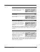
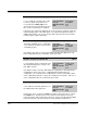
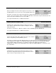
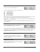
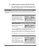
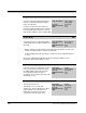
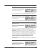
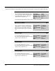
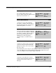
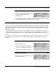
Table Of Contents
- S-3056-1 Distributed Power System SA3100 Drive Configuration and Programming Instruction Manual
- Important User Information
- Contents
- List of Figures
- List of Tables
- Chapter 1 Introduction
- Chapter 2 Configuring the UDC Module, Regulator Type, and Parameters
- 2.1 Adding a Universal Drive Controller (UDC) Module
- 2.2 Entering the Drive Parameters
- 2.3 Configuring the Vector with Constant Power Regulator
- 2.4 Configuring the Volts per Hertz (V/Hz) Regulator
- 2.5 Configuring Flex I/O
- 2.6 Generating Drive Parameter Files and Printing Drive Parameters
- Chapter 3 Configuring the UDC Module’s Registers
- 3.1 Register and Bit Reference Conventions Used in this Manual
- 3.2 Flex I/O Port Registers (Registers 0-23)
- 3.3 UDC/PMI Communication Status Registers (Registers 80-89/1080-1089)
- 3.4 Command Registers (Registers 100-199/1100-1199)
- 3.5 Feedback Registers (Registers 200-299/1200-1299)
- 3.6 Application Registers (Registers 300-599, Every Scan) (Registers 1300-1599, Every Nth Scan)
- 3.7 UDC Module Test I/O Registers (Registers 1000-1017)
- 3.8 Interrupt Status and Control Registers (Registers 2000-2047)
- Chapter 4 Application Programming for DPS Drive Control
- Chapter 5 On-Line Operation
- Appendix A SA3100 Vector Regulator Register Reference
- Appendix B SA3100 Volts / Hertz Regulator Register Reference
- Appendix C SA3100 Local Tunable Variables
- Appendix D Vector with Constant Power Regulator
- Appendix E Volts per Hertz (V/Hz) Regulator
- Appendix F Status of Data in the AutoMax Rack After a STOP_ALL Command or STOP_ALL Fault
- Appendix G Torque Overload Ratio Parameter Precautions
- Appendix H Default Carrier Frequency and Carrier Frequency Limit for Drive Horsepower Ranges
- Appendix I Vector with Constant Power Parameter Entry Example
- Index
3-26
SA3100 Drive Configuration and Programming
Bridge Test Code Register 105/1105
The value written to the Bridge Test Code register determines which
power device to turn on during the bridge test.
Sug. Var. Name: TST_CODE%
Units: N/A
Range: N/A
Access: Read/Write
The six least significant bits correspond to the six power devices:
Bit 0 U Upper Power Device
Bit 1 V Upper Power Device
Bit 2 W Upper Power Device
Bit 3 U Lower Power Device
Bit 4 V Lower Power Device
Bit 5 W Lower Power Device
Patterns that turn on the same device in the upper and lower bridge are not accepted, and no device will be
turned on. Bit 4 in the Drive Warning register (203/1203) is set if an illegal pattern is used.
When a value of -1 is entered in this register, the test will cycle through each power device individually in the
following order: U-, U+, V-, V+, W-, W+.
Refer to the SA3100 Diagnostics, Troubleshooting, and Start-Up Guidelines (S-3059) for more information
about the bridge test.
PMI D/A Output Register 106/1106
The value in the PMI D/A Output Register can be displayed on one of
the four PMI Regulator meter ports. See section 3.6.2.
Sug. Var. Name: PMI_DA%
Units: See below
Range: See below
Access: Read/Write
This register can contain any variable in the AutoMax system as long as it is a 16-bit integer. Double-integer
or floating point values cannot be displayed on the PMI Regulator’s D/A meter ports. The desired value must
be copied into this register by an application task. The value in the register is transmitted to the PMI
Regulator at the end of every scan.
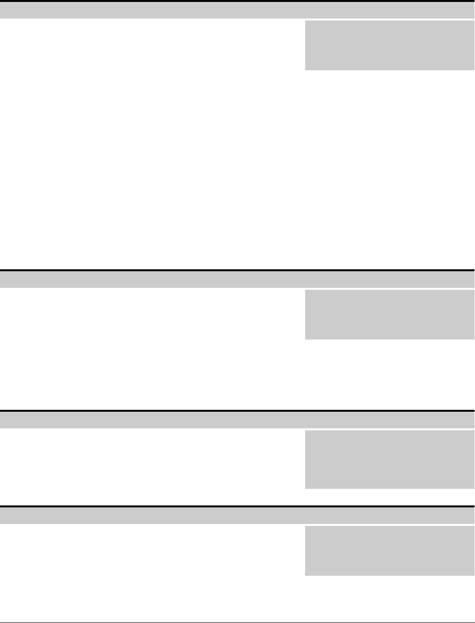
Synchronous Transfer Volts Register* 107/1107
*Reserved for future use.
The Synchronous Transfer Volts register is used during a
synchronous transfer to hold the value of the external voltage source.
The value is scaled in volts.
Sug. Var. Name: SA_V%
Units: Volts
Range: N/A
Access: Read/Write
DC Braking Reference Register 108/1108
The value in the DC Braking Reference register regulates the
magnitude of braking current that is output when the BRK_ON@
signal (register 100, bit 5) is asserted.
Sug. Var. Name: BRK_REF%
Units: Amps ∗ 10
Range: Motor rated amps
Access: Read/Write