
Instruction Manual
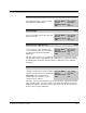
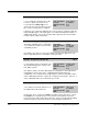
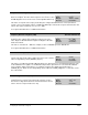
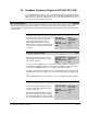
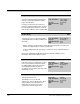
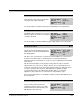
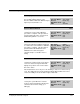
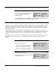
Table Of Contents
- S-3056-1 Distributed Power System SA3100 Drive Configuration and Programming Instruction Manual
- Important User Information
- Contents
- List of Figures
- List of Tables
- Chapter 1 Introduction
- Chapter 2 Configuring the UDC Module, Regulator Type, and Parameters
- 2.1 Adding a Universal Drive Controller (UDC) Module
- 2.2 Entering the Drive Parameters
- 2.3 Configuring the Vector with Constant Power Regulator
- 2.4 Configuring the Volts per Hertz (V/Hz) Regulator
- 2.5 Configuring Flex I/O
- 2.6 Generating Drive Parameter Files and Printing Drive Parameters
- Chapter 3 Configuring the UDC Module’s Registers
- 3.1 Register and Bit Reference Conventions Used in this Manual
- 3.2 Flex I/O Port Registers (Registers 0-23)
- 3.3 UDC/PMI Communication Status Registers (Registers 80-89/1080-1089)
- 3.4 Command Registers (Registers 100-199/1100-1199)
- 3.5 Feedback Registers (Registers 200-299/1200-1299)
- 3.6 Application Registers (Registers 300-599, Every Scan) (Registers 1300-1599, Every Nth Scan)
- 3.7 UDC Module Test I/O Registers (Registers 1000-1017)
- 3.8 Interrupt Status and Control Registers (Registers 2000-2047)
- Chapter 4 Application Programming for DPS Drive Control
- Chapter 5 On-Line Operation
- Appendix A SA3100 Vector Regulator Register Reference
- Appendix B SA3100 Volts / Hertz Regulator Register Reference
- Appendix C SA3100 Local Tunable Variables
- Appendix D Vector with Constant Power Regulator
- Appendix E Volts per Hertz (V/Hz) Regulator
- Appendix F Status of Data in the AutoMax Rack After a STOP_ALL Command or STOP_ALL Fault
- Appendix G Torque Overload Ratio Parameter Precautions
- Appendix H Default Carrier Frequency and Carrier Frequency Limit for Drive Horsepower Ranges
- Appendix I Vector with Constant Power Parameter Entry Example
- Index

Configuring the UDC Module’s Registers
3-27
3.5 Feedback Registers (Registers 200-299/1200-1299)
The Feedback Registers view is used to configure the feedback registers that display
the current status of the drive. These registers are updated by the PMI and sent to the
UDC module over the fiber-optic link before every scan of the UDC task. The status of
these registers is retained after a Stop All.
Drive Status Register 200/1200
The bits in the Drive Status register indicate the current state of the drive. They reflect the status of the
activity initiated through the Drive Control Register (register 100/1100). All the bits in this register are written
to by the PMI.
Torque / Frequency Control OnBit 0
The PMI sets the Torque Control On (Vector
mode) or Frequency Control On (V/Hz
mode) status bit in response to the
PMI_RUN@ command after all of the
interlock tests are passed to indicate that
the minor loop is running and the motor is
energized.
Hex Value: 0001H
Sug. Var. Name: TRQ_ON@ or
FRQ_ON@
Access: Read only
UDC Error Code: N/A
LED: N/A
Automatic Tuning Complete Bit 1
The PMI sets the Automatic Tuning
Complete status bit in response to the
PMI_TUN@ command when the tuning
procedure is complete.
Hex Value: 0002H
Sug. Var. Name: PMI_ATC@
Access: Read only
UDC Error Code: N/A
LED: N/A
In Vector mode, the PMI processor sets this bit to indicate that the calculations for
local tunables STATOR_R_E4% (stator resistance), STATOR_T_E4% (stator time
constant), and STATOR_IZ_E1% (no load stator current) are complete.
In Volts per Hertz mode, the PMI processor sets this bit when the Reset V/Hz Curve
Point Gains procedure is complete. The bit is turned off when PMI_TUN@ is turned
off.
Refer to Appendix B for more information on the local tunables and gains variables.
Torque / Frequency Reference Saturation Plus Bit 2
In Vector mode, the PMI sets the Torque
Reference Saturation Plus bit when the
system is requesting maximum positive
torque from the drive.
In Volts per Hertz mode, the Frequency
Reference Saturation Plus bit is set when
the current limit option has been selected,
and current feedback is at the positive limit.
Hex Value: 0004H
Sug. Var. Name: TRF_SP@ or
FRF_SP@
Access: Read only
UDC Error Code: N/A
LED: N/A