
Instruction Manual
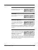
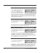
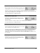
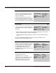
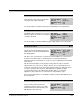
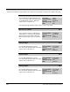
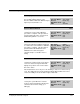
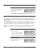
Table Of Contents
- S-3056-1 Distributed Power System SA3100 Drive Configuration and Programming Instruction Manual
- Important User Information
- Contents
- List of Figures
- List of Tables
- Chapter 1 Introduction
- Chapter 2 Configuring the UDC Module, Regulator Type, and Parameters
- 2.1 Adding a Universal Drive Controller (UDC) Module
- 2.2 Entering the Drive Parameters
- 2.3 Configuring the Vector with Constant Power Regulator
- 2.4 Configuring the Volts per Hertz (V/Hz) Regulator
- 2.5 Configuring Flex I/O
- 2.6 Generating Drive Parameter Files and Printing Drive Parameters
- Chapter 3 Configuring the UDC Module’s Registers
- 3.1 Register and Bit Reference Conventions Used in this Manual
- 3.2 Flex I/O Port Registers (Registers 0-23)
- 3.3 UDC/PMI Communication Status Registers (Registers 80-89/1080-1089)
- 3.4 Command Registers (Registers 100-199/1100-1199)
- 3.5 Feedback Registers (Registers 200-299/1200-1299)
- 3.6 Application Registers (Registers 300-599, Every Scan) (Registers 1300-1599, Every Nth Scan)
- 3.7 UDC Module Test I/O Registers (Registers 1000-1017)
- 3.8 Interrupt Status and Control Registers (Registers 2000-2047)
- Chapter 4 Application Programming for DPS Drive Control
- Chapter 5 On-Line Operation
- Appendix A SA3100 Vector Regulator Register Reference
- Appendix B SA3100 Volts / Hertz Regulator Register Reference
- Appendix C SA3100 Local Tunable Variables
- Appendix D Vector with Constant Power Regulator
- Appendix E Volts per Hertz (V/Hz) Regulator
- Appendix F Status of Data in the AutoMax Rack After a STOP_ALL Command or STOP_ALL Fault
- Appendix G Torque Overload Ratio Parameter Precautions
- Appendix H Default Carrier Frequency and Carrier Frequency Limit for Drive Horsepower Ranges
- Appendix I Vector with Constant Power Parameter Entry Example
- Index
3-30
SA3100 Drive Configuration and Programming
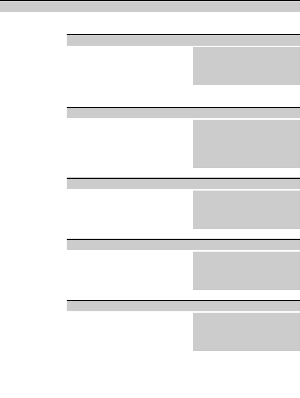
I/O Status Register 201/1201
The bits in the I/O Status register indicate the current state of the inputs on the Resolver & Drive I/O board.
Run Permissive Input Bit 0
The Run Permissive Input bit displays the
status of the input signal connected to pin A
on the DRIVE I/O connector. When the
signal is present, this bit is set.
Hex Value: 0001H
Sug. Var. Name: RPI@
Access: Read only
UDC Error Code: N/A
LED: RPI
This signal typically originates from the drive’s coast-to-stop circuit.
M-Contactor Feedback Bit 1
The M-Contactor Feedback bit reflects the
status of the M-contactor feedback input
signal, which is connected to the AUX IN1
input on the Resolver & Drive I/O board.
When the input signal is present, this bit is
set.
Hex Value: 0002H
Sug. Var. Name: M_FDBK@
Access: Read only
UDC Error Code: N/A
LED: AUX IN1
Auxiliary Input 2 Bit 2
The Auxiliary Input 2 bit reflects the status of
the 115 VAC auxiliary input 2 on the
Resolver & Drive I/O board. When the input
signal is present, this bit is set.
Hex Value: 0004H
Sug. Var. Name: AU_INX2@
Access: Read only
UDC Error Code: N/A
LED: AUX IN2
Auxiliary Input 3 Bit 3
The Auxiliary Input 3 bit reflects the status of
the 115 VAC auxiliary input 3 on the
Resolver & Drive I/O board. When the input
signal is present, this bit is set.
Hex Value: 0008H
Sug. Var. Name: AUX_IN3@
Access: Read only
UDC Error Code: N/A
LED: AUX IN3
Auxiliary Input 4 Bit 4
The Auxiliary Input 4 bit reflects the status of
the 115 VAC auxiliary input 4 on the
Resolver & Drive I/O board. When the input
signal is present, this bit is set.
Hex Value: 0010H
Sug. Var. Name: AUX_IN4@
Access: Read only
UDC Error Code: N/A
LED: AUX IN4