
Instruction Manual
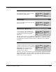
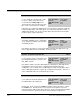
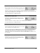
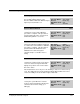
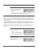
Table Of Contents
- S-3056-1 Distributed Power System SA3100 Drive Configuration and Programming Instruction Manual
- Important User Information
- Contents
- List of Figures
- List of Tables
- Chapter 1 Introduction
- Chapter 2 Configuring the UDC Module, Regulator Type, and Parameters
- 2.1 Adding a Universal Drive Controller (UDC) Module
- 2.2 Entering the Drive Parameters
- 2.3 Configuring the Vector with Constant Power Regulator
- 2.4 Configuring the Volts per Hertz (V/Hz) Regulator
- 2.5 Configuring Flex I/O
- 2.6 Generating Drive Parameter Files and Printing Drive Parameters
- Chapter 3 Configuring the UDC Module’s Registers
- 3.1 Register and Bit Reference Conventions Used in this Manual
- 3.2 Flex I/O Port Registers (Registers 0-23)
- 3.3 UDC/PMI Communication Status Registers (Registers 80-89/1080-1089)
- 3.4 Command Registers (Registers 100-199/1100-1199)
- 3.5 Feedback Registers (Registers 200-299/1200-1299)
- 3.6 Application Registers (Registers 300-599, Every Scan) (Registers 1300-1599, Every Nth Scan)
- 3.7 UDC Module Test I/O Registers (Registers 1000-1017)
- 3.8 Interrupt Status and Control Registers (Registers 2000-2047)
- Chapter 4 Application Programming for DPS Drive Control
- Chapter 5 On-Line Operation
- Appendix A SA3100 Vector Regulator Register Reference
- Appendix B SA3100 Volts / Hertz Regulator Register Reference
- Appendix C SA3100 Local Tunable Variables
- Appendix D Vector with Constant Power Regulator
- Appendix E Volts per Hertz (V/Hz) Regulator
- Appendix F Status of Data in the AutoMax Rack After a STOP_ALL Command or STOP_ALL Fault
- Appendix G Torque Overload Ratio Parameter Precautions
- Appendix H Default Carrier Frequency and Carrier Frequency Limit for Drive Horsepower Ranges
- Appendix I Vector with Constant Power Parameter Entry Example
- Index

3-32
SA3100 Drive Configuration and Programming
I/O Status Register (Continued) 201/1201
STATOR_IZ_E1% Tuning Complete (Vector with Constant Power) Bit 10
The STATOR_IZ_E1% Tuning Complete
status bit is set to indicate that the system
has successfully tuned the value in
STATOR_IZ_E1%.
Hex Value: 0400H
Sug. Var. Name: TUNED_IZ@
Access: Read only
UDC Error Code: N/A
LED: N/A
Note that this procedure is used in Vector with Constant Power applications only.
Refer to Appendix B for more information on this procedure.
Drive Fault Register 202/1202
The bits in the Drive Fault register indicate the cause of a drive shutdown. The bits in this register are latched
until they are reset by setting the Fault Reset bit (bit 8) of the Drive Control register (100/1100, bit 8). After
turning the Fault Reset bit on, the drive may be re-started after turning the desired command bit in register
100/1100 off and then back on again. If the fault condition still exists, the identifying bit in this register will
immediately set again.
The fault conditions reported in this register result in turning off the drive. The UDC task is not stopped
automatically if a drive fault occurs unless it is specifically instructed to in the application task. The user must
ensure that the AutoMax application task tests register 202/1202 and takes appropriate action if a fault
occurs.
Note that the status of this register is also reported in the error log for the task in which the error occurred.
Most faults reported in this register are also indicated by the EXT FLT or P.M. FLT LEDs on the PMI
Regulator.
DC Bus Overvoltage Fault Bit 0
The DC Bus Overvoltage Fault bit is set if
DC bus voltage exceeds:
• 396 volts for 230 VAC Power Modules
• 789 volts for 460 VAC Power Modules
• 986 volts for 575 VAC Power Modules
Hex Value: 0001H
Sug. Var. Name: FLT_OV@
Access: Read only
UDC Error Code: 1018
LED: EXT FLT
DC Bus Overcurrent Fault Bit 1
The DC Bus Overcurrent Fault bit is set if
DC bus current exceeds 125% of the rated
Power Module current.
Hex Value: 0002H
Sug. Var. Name: FLT_DCI@
Access: Read only
UDC Error Code: 1020
LED: P.M. FLT