
Instruction Manual
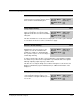
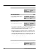
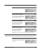
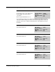
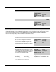
Table Of Contents
- S-3056-1 Distributed Power System SA3100 Drive Configuration and Programming Instruction Manual
- Important User Information
- Contents
- List of Figures
- List of Tables
- Chapter 1 Introduction
- Chapter 2 Configuring the UDC Module, Regulator Type, and Parameters
- 2.1 Adding a Universal Drive Controller (UDC) Module
- 2.2 Entering the Drive Parameters
- 2.3 Configuring the Vector with Constant Power Regulator
- 2.4 Configuring the Volts per Hertz (V/Hz) Regulator
- 2.5 Configuring Flex I/O
- 2.6 Generating Drive Parameter Files and Printing Drive Parameters
- Chapter 3 Configuring the UDC Module’s Registers
- 3.1 Register and Bit Reference Conventions Used in this Manual
- 3.2 Flex I/O Port Registers (Registers 0-23)
- 3.3 UDC/PMI Communication Status Registers (Registers 80-89/1080-1089)
- 3.4 Command Registers (Registers 100-199/1100-1199)
- 3.5 Feedback Registers (Registers 200-299/1200-1299)
- 3.6 Application Registers (Registers 300-599, Every Scan) (Registers 1300-1599, Every Nth Scan)
- 3.7 UDC Module Test I/O Registers (Registers 1000-1017)
- 3.8 Interrupt Status and Control Registers (Registers 2000-2047)
- Chapter 4 Application Programming for DPS Drive Control
- Chapter 5 On-Line Operation
- Appendix A SA3100 Vector Regulator Register Reference
- Appendix B SA3100 Volts / Hertz Regulator Register Reference
- Appendix C SA3100 Local Tunable Variables
- Appendix D Vector with Constant Power Regulator
- Appendix E Volts per Hertz (V/Hz) Regulator
- Appendix F Status of Data in the AutoMax Rack After a STOP_ALL Command or STOP_ALL Fault
- Appendix G Torque Overload Ratio Parameter Precautions
- Appendix H Default Carrier Frequency and Carrier Frequency Limit for Drive Horsepower Ranges
- Appendix I Vector with Constant Power Parameter Entry Example
- Index

Configuring the UDC Module’s Registers
3-33
Drive Fault Register (Continued) 202/1202
Ground Current Fault Bit 2
The Ground Current Fault bit is set if ground
current exceeds the hardware trip point.
Hex Value: 0004H
Sug. Var. Name: FLT_GND@
Access: Read only
UDC Error Code: 1021
LED: EXT FLT
For models A001/Q001 and A003/Q003 the hardware trip point is 20A @ 10V.
For all other models it is 100A @ 10V.
Instantaneous Overcurrent Fault Bit 3
The Instantaneous Overcurrent (IOC) Fault
bit is set if either of the following conditions
is detected:
Hex Value: 0008H
Sug. Var. Name: FLT_IOC@
Access: Read only
UDC Error Code: 1017
LED: P.M. FLT
• Output current is greater than 200% of the peak RMS current. Bits 0 to 5 in
register 204/1204 indicate which power device detected the overcurrent.
• An inverter power device fault is detected. Bit 6 in register 204/1204 will be set if
the IOC fault is due to a power device overcurrent.
Power Supply Fault Bit 4
The Power Supply Fault bit is set if the
output of the isolated +12V supply, or the
output of the external power supply for a G
or H frame drive, falls below the configured
low voltage threshold.
Hex Value: 0010H
Sug. Var. Name: FLT_12V@
Access: Read only
UDC Error Code: 1022
LED: P.M. FLT
Register 222/1222 provides additional diagnostics if this fault occurs.
Bit 5
Reserved for future use.
Hex Value: 0020H
Sug. Var. Name:
Access: Read only
UDC Error Code: 1023
LED: