
Instruction Manual
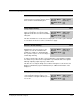
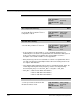
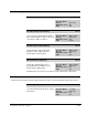
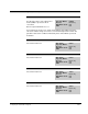
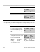
Table Of Contents
- S-3056-1 Distributed Power System SA3100 Drive Configuration and Programming Instruction Manual
- Important User Information
- Contents
- List of Figures
- List of Tables
- Chapter 1 Introduction
- Chapter 2 Configuring the UDC Module, Regulator Type, and Parameters
- 2.1 Adding a Universal Drive Controller (UDC) Module
- 2.2 Entering the Drive Parameters
- 2.3 Configuring the Vector with Constant Power Regulator
- 2.4 Configuring the Volts per Hertz (V/Hz) Regulator
- 2.5 Configuring Flex I/O
- 2.6 Generating Drive Parameter Files and Printing Drive Parameters
- Chapter 3 Configuring the UDC Module’s Registers
- 3.1 Register and Bit Reference Conventions Used in this Manual
- 3.2 Flex I/O Port Registers (Registers 0-23)
- 3.3 UDC/PMI Communication Status Registers (Registers 80-89/1080-1089)
- 3.4 Command Registers (Registers 100-199/1100-1199)
- 3.5 Feedback Registers (Registers 200-299/1200-1299)
- 3.6 Application Registers (Registers 300-599, Every Scan) (Registers 1300-1599, Every Nth Scan)
- 3.7 UDC Module Test I/O Registers (Registers 1000-1017)
- 3.8 Interrupt Status and Control Registers (Registers 2000-2047)
- Chapter 4 Application Programming for DPS Drive Control
- Chapter 5 On-Line Operation
- Appendix A SA3100 Vector Regulator Register Reference
- Appendix B SA3100 Volts / Hertz Regulator Register Reference
- Appendix C SA3100 Local Tunable Variables
- Appendix D Vector with Constant Power Regulator
- Appendix E Volts per Hertz (V/Hz) Regulator
- Appendix F Status of Data in the AutoMax Rack After a STOP_ALL Command or STOP_ALL Fault
- Appendix G Torque Overload Ratio Parameter Precautions
- Appendix H Default Carrier Frequency and Carrier Frequency Limit for Drive Horsepower Ranges
- Appendix I Vector with Constant Power Parameter Entry Example
- Index
3-36
SA3100 Drive Configuration and Programming
Drive Fault Register (Continued) 202/1202
Communication Lost Fault Bit 15
The Communication Lost Fault bit is set if
the fiber-optic communication between the
PMI Processor and the UDC module is lost
due to two consecutive errors of any type.
Hex Value: 8000H
Sug. Var. Name: FLT_COM@
Access: Read only
UDC Error Code: 1015
LED: COMM OK
This bit is set only after communication between the PMI Regulator and UDC
module has been established. This bit should be used in the run permissive logic for
the drive. Also refer to the CCLK Synchronized bit (register 200/1200, bit 14).
Drive Warning Register 203/1203
The warnings indicated by the Drive Warning register cause no action by themselves. Any resulting action is
determined by the application task. The user must ensure that the AutoMax application task monitors
register 203/1203 and takes appropriate action if any of these conditions occurs. If a warning condition is
detected, the corresponding bit is latched until the Warning Reset bit (bit 9) of the Drive Control register
(register 100/1100) is set.
DC Bus Overvoltage Warning Bit 0
The DC Bus Overvoltage Warning bit is set
if the DC bus voltage rises above the
overvoltage threshold value stored in local
tunable OVT_E0%.
Hex Value: 0001H
Sug. Var. Name: WRN_OV@
Access: Read only
UDC Error Code: N/A
LED: N/A
The torque is automatically limited to avoid an overvoltage fault. Bit 4 of the Drive
Warning register will also be set to indicate the torque is being limited by the
system. Refer to the SA3100 Power Modules instruction manual (S-3058) for more
information about internal DC bus control.
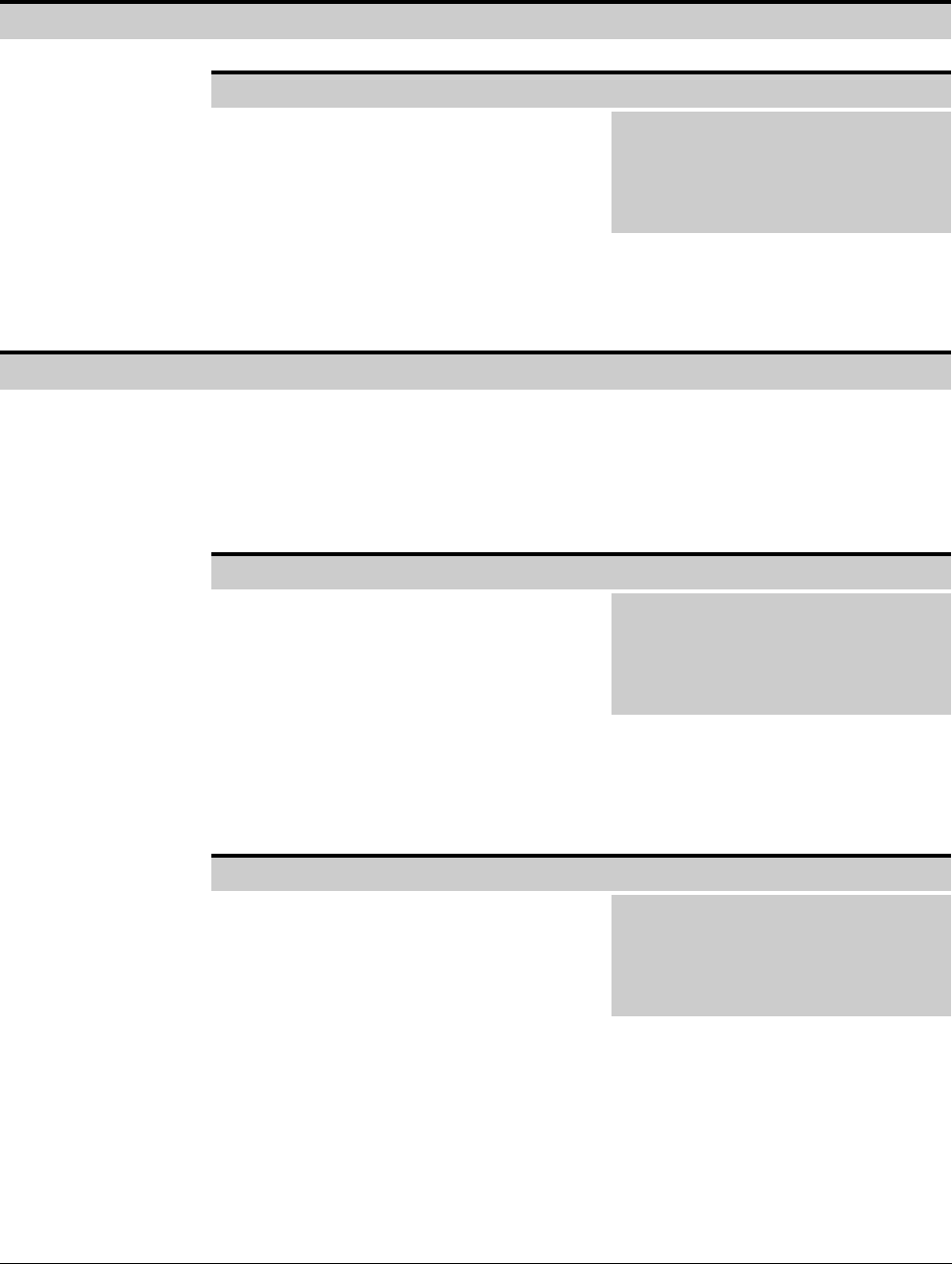
DC Bus Undervoltage Warning Bit 1
The DC Bus Undervoltage Warning bit is set
if the DC bus voltage drops below the
undervoltage threshold stored in local
tunable UVT_E0%.
Hex Value: 0002H
Sug. Var. Name: WRN_UV@
Access: Read only
UDC Error Code: N/A
LED: N/A
The torque is automatically limited to avoid an undervoltage fault. Bit 4 of the Drive
Warning register will also be set to indicate the torque is being limited by the
system. Refer to the SA3100 Power Modules instruction manual (S-3058) for more
information about internal DC bus control.