
Instruction Manual
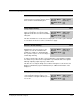
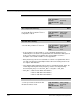
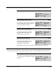
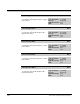
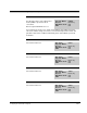
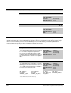
Table Of Contents
- S-3056-1 Distributed Power System SA3100 Drive Configuration and Programming Instruction Manual
- Important User Information
- Contents
- List of Figures
- List of Tables
- Chapter 1 Introduction
- Chapter 2 Configuring the UDC Module, Regulator Type, and Parameters
- 2.1 Adding a Universal Drive Controller (UDC) Module
- 2.2 Entering the Drive Parameters
- 2.3 Configuring the Vector with Constant Power Regulator
- 2.4 Configuring the Volts per Hertz (V/Hz) Regulator
- 2.5 Configuring Flex I/O
- 2.6 Generating Drive Parameter Files and Printing Drive Parameters
- Chapter 3 Configuring the UDC Module’s Registers
- 3.1 Register and Bit Reference Conventions Used in this Manual
- 3.2 Flex I/O Port Registers (Registers 0-23)
- 3.3 UDC/PMI Communication Status Registers (Registers 80-89/1080-1089)
- 3.4 Command Registers (Registers 100-199/1100-1199)
- 3.5 Feedback Registers (Registers 200-299/1200-1299)
- 3.6 Application Registers (Registers 300-599, Every Scan) (Registers 1300-1599, Every Nth Scan)
- 3.7 UDC Module Test I/O Registers (Registers 1000-1017)
- 3.8 Interrupt Status and Control Registers (Registers 2000-2047)
- Chapter 4 Application Programming for DPS Drive Control
- Chapter 5 On-Line Operation
- Appendix A SA3100 Vector Regulator Register Reference
- Appendix B SA3100 Volts / Hertz Regulator Register Reference
- Appendix C SA3100 Local Tunable Variables
- Appendix D Vector with Constant Power Regulator
- Appendix E Volts per Hertz (V/Hz) Regulator
- Appendix F Status of Data in the AutoMax Rack After a STOP_ALL Command or STOP_ALL Fault
- Appendix G Torque Overload Ratio Parameter Precautions
- Appendix H Default Carrier Frequency and Carrier Frequency Limit for Drive Horsepower Ranges
- Appendix I Vector with Constant Power Parameter Entry Example
- Index

Configuring the UDC Module’s Registers
3-41
Power Device Status Register (Continued) 204/1204
Inverter Power Device Fault Bit 6
The Inverter Power Device Fault bit is set if
the gate driver turns off an output power
device (IGBT) to protect it from an
overcurrent.
Bit 3 in register 202 will also be set.
Hex Value: 0040H
Sug. Var. Name: IPMA@
Access: Read only
UDC Error Code: N/A
LED: N/A
If an output short circuit occurs, a high current will flow in the IGBT causing its
collector-to-emitter voltage to increase to a level much higher than normal. The
gate driver detects this condition and instantly shuts off the IGBT to prevent its
destruction.
Bit 7
Reserved for future use.
Hex Value: 0080H
Sug. Var. Name:
Access: Read only
UDC Error Code: N/A
LED: N/A
Bit 8
Reserved for future use.
Hex Value: 0100H
Sug. Var. Name:
Access: Read only
UDC Error Code: N/A
LED: N/A
Bit 12
Reserved for future use.
Hex Value: 1000H
Sug. Var. Name:
Access: Read only
UDC Error Code: N/A
LED: N/A
Bit 13
Reserved for future use.
.
Hex Value: 2000H
Sug. Var. Name:
Access: Read only
UDC Error Code: N/A
LED: N/A