
Instruction Manual
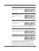
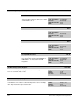
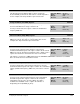

Table Of Contents
- S-3056-1 Distributed Power System SA3100 Drive Configuration and Programming Instruction Manual
- Important User Information
- Contents
- List of Figures
- List of Tables
- Chapter 1 Introduction
- Chapter 2 Configuring the UDC Module, Regulator Type, and Parameters
- 2.1 Adding a Universal Drive Controller (UDC) Module
- 2.2 Entering the Drive Parameters
- 2.3 Configuring the Vector with Constant Power Regulator
- 2.4 Configuring the Volts per Hertz (V/Hz) Regulator
- 2.5 Configuring Flex I/O
- 2.6 Generating Drive Parameter Files and Printing Drive Parameters
- Chapter 3 Configuring the UDC Module’s Registers
- 3.1 Register and Bit Reference Conventions Used in this Manual
- 3.2 Flex I/O Port Registers (Registers 0-23)
- 3.3 UDC/PMI Communication Status Registers (Registers 80-89/1080-1089)
- 3.4 Command Registers (Registers 100-199/1100-1199)
- 3.5 Feedback Registers (Registers 200-299/1200-1299)
- 3.6 Application Registers (Registers 300-599, Every Scan) (Registers 1300-1599, Every Nth Scan)
- 3.7 UDC Module Test I/O Registers (Registers 1000-1017)
- 3.8 Interrupt Status and Control Registers (Registers 2000-2047)
- Chapter 4 Application Programming for DPS Drive Control
- Chapter 5 On-Line Operation
- Appendix A SA3100 Vector Regulator Register Reference
- Appendix B SA3100 Volts / Hertz Regulator Register Reference
- Appendix C SA3100 Local Tunable Variables
- Appendix D Vector with Constant Power Regulator
- Appendix E Volts per Hertz (V/Hz) Regulator
- Appendix F Status of Data in the AutoMax Rack After a STOP_ALL Command or STOP_ALL Fault
- Appendix G Torque Overload Ratio Parameter Precautions
- Appendix H Default Carrier Frequency and Carrier Frequency Limit for Drive Horsepower Ranges
- Appendix I Vector with Constant Power Parameter Entry Example
- Index
Configuring the UDC Module’s Registers
3-43
Interlock Register (Continued) 205/1205
RPI Missing Bit 2
The RPI Missing bit is set if the Run
Permissive input on the Resolver & Drive
I/O board is not on.
Hex Value: 0004H
Sug. Var. Name: IC_RPI@
Access: Read only
UDC Error Code: N/A
LED: N/A
Faults Need Reset Bit 3
The Faults Need Reset bit is set if previous
faults (register 202/1202) have not been
cleared.
Hex Value: 0008H
Sug. Var. Name: IC_FLT@
Access: Read only
UDC Error Code: N/A
LED: N/A
Rising Edge Required Bit 4
The Rising Edge Required bit is set if a
rising edge is not detected on a command
bit in register 100/1100.
Hex Value: 0010H
Sug. Var. Name: IC_RISE@
Access: Read only
UDC Error Code: N/A
LED: N/A
This interlock bit will be set if the application task has set the Fault Reset bit (register
100/1100, bit 8) but has not cleared and then re-enabled any command bits.
More Than One Request Bit 5
The More Than One Request bit is set if
more than one operating mode is requested
at a time in register 100/1100 (bits 0, 1, 2).
Hex Value: 0020H
Sug. Var. Name: IC_MORE@
Access: Read only
UDC Error Code: N/A
LED: N/A
Bus Not Ready Bit 6
The Bus Not Ready bit is set when turning
on the drive if the DC bus is not ready.
Hex Value: 0040H
Sug. Var. Name: IC_BUS@
Access: Read only
UDC Error Code: N/A
LED: N/A
The bus is ready when the DC bus voltage is greater than the undervoltage
threshold value stored in local tunable UVT_E0% and has reached a steady state,
and feedback indicates that the pre-charge contactor has closed.
This interlock bit will also be set when turning on the drive if the bus enable bit
(register 100/1100, bit 4) has not been set. Refer to the SA3100 Power Modules
instruction manual (S-3058) for more information about internal DC bus control.