
Instruction Manual
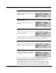
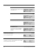
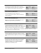
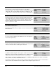
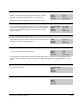
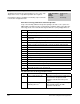
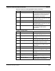
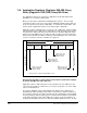

Table Of Contents
- S-3056-1 Distributed Power System SA3100 Drive Configuration and Programming Instruction Manual
- Important User Information
- Contents
- List of Figures
- List of Tables
- Chapter 1 Introduction
- Chapter 2 Configuring the UDC Module, Regulator Type, and Parameters
- 2.1 Adding a Universal Drive Controller (UDC) Module
- 2.2 Entering the Drive Parameters
- 2.3 Configuring the Vector with Constant Power Regulator
- 2.4 Configuring the Volts per Hertz (V/Hz) Regulator
- 2.5 Configuring Flex I/O
- 2.6 Generating Drive Parameter Files and Printing Drive Parameters
- Chapter 3 Configuring the UDC Module’s Registers
- 3.1 Register and Bit Reference Conventions Used in this Manual
- 3.2 Flex I/O Port Registers (Registers 0-23)
- 3.3 UDC/PMI Communication Status Registers (Registers 80-89/1080-1089)
- 3.4 Command Registers (Registers 100-199/1100-1199)
- 3.5 Feedback Registers (Registers 200-299/1200-1299)
- 3.6 Application Registers (Registers 300-599, Every Scan) (Registers 1300-1599, Every Nth Scan)
- 3.7 UDC Module Test I/O Registers (Registers 1000-1017)
- 3.8 Interrupt Status and Control Registers (Registers 2000-2047)
- Chapter 4 Application Programming for DPS Drive Control
- Chapter 5 On-Line Operation
- Appendix A SA3100 Vector Regulator Register Reference
- Appendix B SA3100 Volts / Hertz Regulator Register Reference
- Appendix C SA3100 Local Tunable Variables
- Appendix D Vector with Constant Power Regulator
- Appendix E Volts per Hertz (V/Hz) Regulator
- Appendix F Status of Data in the AutoMax Rack After a STOP_ALL Command or STOP_ALL Fault
- Appendix G Torque Overload Ratio Parameter Precautions
- Appendix H Default Carrier Frequency and Carrier Frequency Limit for Drive Horsepower Ranges
- Appendix I Vector with Constant Power Parameter Entry Example
- Index

Configuring the UDC Module’s Registers
3-45
Ground Current Feedback (Amps) Register 208/1208
The Ground Current Feedback (Amps) register contains the
measured RMS ground current. This value is scaled in amps times
10. For example, 50.1 amps would be represented as 501.
Sug. Var. Name: GI_FB%
Units: Amps
∗
10
Range: N/A
Access: Read only
Voltage Feedback (Volts RMS) Register 209/1209
In Vector mode, the Voltage Feedback (Volts RMS) register contains
the measured RMS motor voltage scaled in volts.
In Volts per Hertz mode, this register contains the fundamental
frequency RMS volts.
Sug. Var. Name: V_FB%
Units: RMS volts
Range: N/A
Access: Read only
Current Feedback (Amps RMS) Register 210/1210
The Current Feedback (Amps RMS) register contains the measured
RMS motor current. This value is scaled in amps times 10. For
example, 50.1 amps would be represented as 501.
Sug. Var. Name: I_FB%
Units: Amps
∗
10
Range: N/A
Access: Read only
Current Feedback Normalized Register (Vector) 211/1211
In Vector mode, register 211/1211 functions as the Current
Feedback Normalized register. This register contains the measured
RMS motor current. The data is normalized so that +/- 4095 counts is
equal to the rated motor current times the motor overload ratio.
Sug. Var. Name: I_FBN%
Units: Counts
Range: +/- 4095
Access: Read only
This register is used as the I_FDBK parameter in the THERMAL OVERLOAD control block used in DPS
drives to monitor the motor for thermal overload.
Volt Command Register (V/Hz) 211/1211
In Volts per Hertz mode, register 211/1211 functions as the Volt
Command feedback register. This register contains the commanded
voltage (fundamental frequency, RMS volts). The value is scaled in
volts.
Sug. Var. Name: V_CMD%
Units: RMS volts
Range:
Access: Read only
Id Feedback Normalized Register (Vector) 212/1212
In Vector mode, register 212/1212 functions as the Id Feedback
Normalized register. This register contains the Id component
(magnetizing current) of the current feedback. The data is
normalized so that 4095 counts is equal to the full value of
magnetizing current (STATOR_IZ_E1%).
Sug. Var. Name: ID_FBN%
Units: Counts
Range: 0 to 4095
Access: Read only