
Instruction Manual
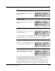
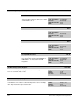
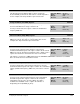
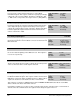

Table Of Contents
- S-3056-1 Distributed Power System SA3100 Drive Configuration and Programming Instruction Manual
- Important User Information
- Contents
- List of Figures
- List of Tables
- Chapter 1 Introduction
- Chapter 2 Configuring the UDC Module, Regulator Type, and Parameters
- 2.1 Adding a Universal Drive Controller (UDC) Module
- 2.2 Entering the Drive Parameters
- 2.3 Configuring the Vector with Constant Power Regulator
- 2.4 Configuring the Volts per Hertz (V/Hz) Regulator
- 2.5 Configuring Flex I/O
- 2.6 Generating Drive Parameter Files and Printing Drive Parameters
- Chapter 3 Configuring the UDC Module’s Registers
- 3.1 Register and Bit Reference Conventions Used in this Manual
- 3.2 Flex I/O Port Registers (Registers 0-23)
- 3.3 UDC/PMI Communication Status Registers (Registers 80-89/1080-1089)
- 3.4 Command Registers (Registers 100-199/1100-1199)
- 3.5 Feedback Registers (Registers 200-299/1200-1299)
- 3.6 Application Registers (Registers 300-599, Every Scan) (Registers 1300-1599, Every Nth Scan)
- 3.7 UDC Module Test I/O Registers (Registers 1000-1017)
- 3.8 Interrupt Status and Control Registers (Registers 2000-2047)
- Chapter 4 Application Programming for DPS Drive Control
- Chapter 5 On-Line Operation
- Appendix A SA3100 Vector Regulator Register Reference
- Appendix B SA3100 Volts / Hertz Regulator Register Reference
- Appendix C SA3100 Local Tunable Variables
- Appendix D Vector with Constant Power Regulator
- Appendix E Volts per Hertz (V/Hz) Regulator
- Appendix F Status of Data in the AutoMax Rack After a STOP_ALL Command or STOP_ALL Fault
- Appendix G Torque Overload Ratio Parameter Precautions
- Appendix H Default Carrier Frequency and Carrier Frequency Limit for Drive Horsepower Ranges
- Appendix I Vector with Constant Power Parameter Entry Example
- Index

3-46
SA3100 Drive Configuration and Programming
Iq Feedback Normalized Register (Vector) 213/1213
In Vector mode, register 213/1213 functions as Iq Feedback
Normalized register. This register contains the Iq (torque producing)
component of the current feedback. The data is normalized so that
+/- 4095 counts corresponds to the torque reference (TRQ_REF%).
Sug. Var. Name: IQ_FBN%
Units: Counts
Range: +/- 4095
Access: Read only
Output Frequency Register (V/Hz) 212/1212 and 213/1213
In Volts per Hertz mode, registers 212/1212 and 213/1213 function
as the Output Frequency register. This double precision register
contains the output frequency value of the drive. Register 212/1212
holds the high word. Register 213/1213 holds the low word. The
value is scaled in Hz
∗
1000.
Sug. Var. Name: F_CMD!
Units: Hz
∗
1000
Range: 0 to 600,000
Access: Read only
User Analog Input Register 214/1214
The User Analog Input register contains the measured user analog
input value from the Resolver Feedback connector on the Resolver &
Drive I/O board.
Sug. Var. Name: ANA_IN%
Units: Counts (Volts)
Range: -2048 to +2047
(-10V to +10V)
Access: Read only
Resolver Scan Position Register 215/1215
The Resolver Scan Position register contains the electrical position of
the resolver at the beginning of the UDC task scan. This register is
reset to zero at power-up.
Sug. V ar. Name: RES_SCN_POS%
Units: Counts
Range: -32768 to +32767
Access: Read only
Resolver Strobe Position Register 216/1216
The Resolver Strobe Position register contains the electrical position
of the resolver at the time a strobe signal is detected.
Sug. Var. Name: RES_STR_POS%
Units: Counts
Range: -32768 to +32767
Access: Read only
Current Feedback Normalized Register (V/Hz) 216/1216
In Volts per Hertz mode, register 216/1216 functions as the Current
Feedback Normalized register. This register contains the measured
RMS motor current. The data is normalized so that +/- 4095 counts is
equal to the rated motor current times the motor overload ratio.
Sug. Var. Name: I_FBN%
Units: Counts
Range: +/- 4095
Access: Read only
This register is used as the I_FDBK parameter in the THERMAL OVERLOAD control block used in DPS
drives to monitor the motor for thermal overload.
Note that the regulator uses a value of 150% overload for this function. If another value of overload ratio is
desired, it must be communicated to the regulator via the dual port register 711/1711.