
Instruction Manual
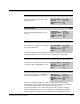
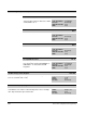
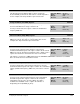
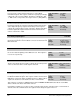
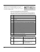
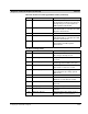

Table Of Contents
- S-3056-1 Distributed Power System SA3100 Drive Configuration and Programming Instruction Manual
- Important User Information
- Contents
- List of Figures
- List of Tables
- Chapter 1 Introduction
- Chapter 2 Configuring the UDC Module, Regulator Type, and Parameters
- 2.1 Adding a Universal Drive Controller (UDC) Module
- 2.2 Entering the Drive Parameters
- 2.3 Configuring the Vector with Constant Power Regulator
- 2.4 Configuring the Volts per Hertz (V/Hz) Regulator
- 2.5 Configuring Flex I/O
- 2.6 Generating Drive Parameter Files and Printing Drive Parameters
- Chapter 3 Configuring the UDC Module’s Registers
- 3.1 Register and Bit Reference Conventions Used in this Manual
- 3.2 Flex I/O Port Registers (Registers 0-23)
- 3.3 UDC/PMI Communication Status Registers (Registers 80-89/1080-1089)
- 3.4 Command Registers (Registers 100-199/1100-1199)
- 3.5 Feedback Registers (Registers 200-299/1200-1299)
- 3.6 Application Registers (Registers 300-599, Every Scan) (Registers 1300-1599, Every Nth Scan)
- 3.7 UDC Module Test I/O Registers (Registers 1000-1017)
- 3.8 Interrupt Status and Control Registers (Registers 2000-2047)
- Chapter 4 Application Programming for DPS Drive Control
- Chapter 5 On-Line Operation
- Appendix A SA3100 Vector Regulator Register Reference
- Appendix B SA3100 Volts / Hertz Regulator Register Reference
- Appendix C SA3100 Local Tunable Variables
- Appendix D Vector with Constant Power Regulator
- Appendix E Volts per Hertz (V/Hz) Regulator
- Appendix F Status of Data in the AutoMax Rack After a STOP_ALL Command or STOP_ALL Fault
- Appendix G Torque Overload Ratio Parameter Precautions
- Appendix H Default Carrier Frequency and Carrier Frequency Limit for Drive Horsepower Ranges
- Appendix I Vector with Constant Power Parameter Entry Example
- Index
3-48
SA3100 Drive Configuration and Programming
AC Power Technology Calibration and Power-Up Faults:
If any of the following calibration and power-up diagnostic faults occurs, replace the
PMI Regulator motherboard. These faults indicate a hardware failure of the AC power
technology circuit on the motherboard. Register 202, bit 11 (FLT_PTM@) will be set.
Run Time AC Power Technology Hardware Faults:
Diagnostic Fault Code Register 222/1222
The Diagnostic Fault Code register displays an error code to help
diagnose the cause of a problem reported in other registers.
Note that this register is available for monitoring only. It cannot be
referenced in an application task.
Sug. Var. Name: DIAG_FLT%
Units: N/A
Range: N/A
Access: Read only
Code Fault
1 D/A high voltage error (+3.3V 10% out of tolerance)
2 D/A low voltage error (-3.3V 10% out of tolerance)
3 Torque current loop proportional gain not within calibration limits
(14<g<30)
4 Flux current loop proportional gain not within calibration limits (14<g<30)
5 Flux current loop integrator time constant not within calibrated limits
6 Torque current loop integrator time constant not within calibrated limits
7 Modulation index error
8 Harmonic DAC limit error
9 Modulation range error
10 Harmonic DAC range error
11 Programmable current limit or the ground fault limit fault
12 Voltage feedback integrator error
13 A/D converter interrupt error
14 Pulse Width Modulator frequency error
15 DC bus current not zero at power-up.
16 Phase U current not zero at power-up.
17 Phase W current not zero at power-up.
Code Fault Description/Action
20 Power supply monitor trip AC power technology power supply level
out of tolerance. Replace the PMI
Regulator motherboard and/or power
supply.
21 AC power technology
watchdog time-out
AC power technology circuit watchdog
timer expired. Replace the PMI
Regulator motherboard.