
Instruction Manual
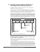

Table Of Contents
- S-3056-1 Distributed Power System SA3100 Drive Configuration and Programming Instruction Manual
- Important User Information
- Contents
- List of Figures
- List of Tables
- Chapter 1 Introduction
- Chapter 2 Configuring the UDC Module, Regulator Type, and Parameters
- 2.1 Adding a Universal Drive Controller (UDC) Module
- 2.2 Entering the Drive Parameters
- 2.3 Configuring the Vector with Constant Power Regulator
- 2.4 Configuring the Volts per Hertz (V/Hz) Regulator
- 2.5 Configuring Flex I/O
- 2.6 Generating Drive Parameter Files and Printing Drive Parameters
- Chapter 3 Configuring the UDC Module’s Registers
- 3.1 Register and Bit Reference Conventions Used in this Manual
- 3.2 Flex I/O Port Registers (Registers 0-23)
- 3.3 UDC/PMI Communication Status Registers (Registers 80-89/1080-1089)
- 3.4 Command Registers (Registers 100-199/1100-1199)
- 3.5 Feedback Registers (Registers 200-299/1200-1299)
- 3.6 Application Registers (Registers 300-599, Every Scan) (Registers 1300-1599, Every Nth Scan)
- 3.7 UDC Module Test I/O Registers (Registers 1000-1017)
- 3.8 Interrupt Status and Control Registers (Registers 2000-2047)
- Chapter 4 Application Programming for DPS Drive Control
- Chapter 5 On-Line Operation
- Appendix A SA3100 Vector Regulator Register Reference
- Appendix B SA3100 Volts / Hertz Regulator Register Reference
- Appendix C SA3100 Local Tunable Variables
- Appendix D Vector with Constant Power Regulator
- Appendix E Volts per Hertz (V/Hz) Regulator
- Appendix F Status of Data in the AutoMax Rack After a STOP_ALL Command or STOP_ALL Fault
- Appendix G Torque Overload Ratio Parameter Precautions
- Appendix H Default Carrier Frequency and Carrier Frequency Limit for Drive Horsepower Ranges
- Appendix I Vector with Constant Power Parameter Entry Example
- Index
3-50
SA3100 Drive Configuration and Programming
3.6 Application Registers (Registers 300-599, Every
Scan) (Registers 1300-1599, Every Nth Scan)
The application registers are used to pass application-specific data between the
AutoMax Processor and the UDC module.
Memory is allocated for a maximum of 600 application registers. There are 300
registers that can be used every scan (registers 300-599) and 300 registers that can
be used every Nth scan (registers 1300-1599). “N” is defined in register 2001. Note
that the status of application registers is not retained after a STOP ALL.
Application registers 300-599 can be used every scan of UDC tasks. Registers within
this range written to by a UDC task are updated by the UDC operating system from its
local memory to dual port memory after each task is run. Registers within this range
written to by an AutoMax task are read by the UDC operating system from dual port
memory and copied into the UDC local memory at the beginning of each scan in order
to have a consistent context for evaluation. See figure 3.1.
Note that the same bits or registers must not be written to (and used as outputs)
by both an AutoMax task and a UDC task.
Application registers 1300-1599 can be used every Nth scan of the UDC task. Nth
scan registers should be used when it is necessary to synchronize one or more UDC
tasks to an AutoMax task.
The registers within this range (1300-1599) that are written to by a UDC task are
updated by the UDC operating system from its local memory to dual port memory at
the end of the scan that occurs before the Nth scan (N-1). At that time, an interrupt will
be generated by the UDC operating system to indicate that new data has been written
to the dual port memory. Refer to the 2000-series registers for more information on
interrupts. An AutoMax task must have defined a hardware EVENT in order to be able
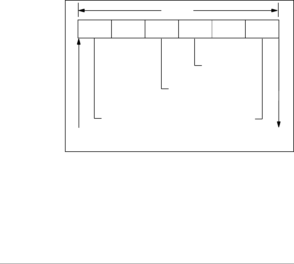
Figure 3.1 – UDC Task Scan
Input A Run A Output A Input B Run B Output B
UDC Scan*
Feedback From PMI
Command to PMI
*Task B can act on Task A outputs within a scan.
Latch “every scan”
registers that are
inputs to task B
Write “every scan”
registers that are
outputs from task A
Latch “every scan”
registers that are
inputs to task A
Write “every scan”
registers that are
outputs from task B