
Instruction Manual
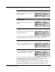
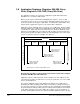

Table Of Contents
- S-3056-1 Distributed Power System SA3100 Drive Configuration and Programming Instruction Manual
- Important User Information
- Contents
- List of Figures
- List of Tables
- Chapter 1 Introduction
- Chapter 2 Configuring the UDC Module, Regulator Type, and Parameters
- 2.1 Adding a Universal Drive Controller (UDC) Module
- 2.2 Entering the Drive Parameters
- 2.3 Configuring the Vector with Constant Power Regulator
- 2.4 Configuring the Volts per Hertz (V/Hz) Regulator
- 2.5 Configuring Flex I/O
- 2.6 Generating Drive Parameter Files and Printing Drive Parameters
- Chapter 3 Configuring the UDC Module’s Registers
- 3.1 Register and Bit Reference Conventions Used in this Manual
- 3.2 Flex I/O Port Registers (Registers 0-23)
- 3.3 UDC/PMI Communication Status Registers (Registers 80-89/1080-1089)
- 3.4 Command Registers (Registers 100-199/1100-1199)
- 3.5 Feedback Registers (Registers 200-299/1200-1299)
- 3.6 Application Registers (Registers 300-599, Every Scan) (Registers 1300-1599, Every Nth Scan)
- 3.7 UDC Module Test I/O Registers (Registers 1000-1017)
- 3.8 Interrupt Status and Control Registers (Registers 2000-2047)
- Chapter 4 Application Programming for DPS Drive Control
- Chapter 5 On-Line Operation
- Appendix A SA3100 Vector Regulator Register Reference
- Appendix B SA3100 Volts / Hertz Regulator Register Reference
- Appendix C SA3100 Local Tunable Variables
- Appendix D Vector with Constant Power Regulator
- Appendix E Volts per Hertz (V/Hz) Regulator
- Appendix F Status of Data in the AutoMax Rack After a STOP_ALL Command or STOP_ALL Fault
- Appendix G Torque Overload Ratio Parameter Precautions
- Appendix H Default Carrier Frequency and Carrier Frequency Limit for Drive Horsepower Ranges
- Appendix I Vector with Constant Power Parameter Entry Example
- Index
3-52
SA3100 Drive Configuration and Programming
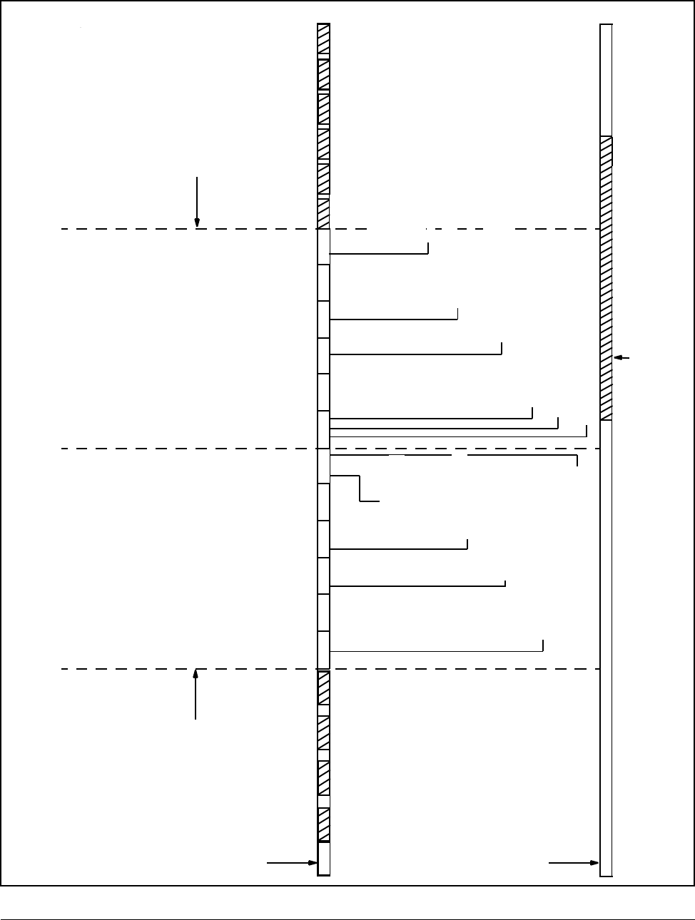
Figure 3.2 – Nth Scan Interrupts
Latch “every scan"
Output BInput A Run A
OutputA
Input B Run B
Scan 1Scan 2 Scan 3 Scan 4
Scan 5
Scan N
(n-1)
Output B
Input A
Run A
OutputA
Input B
Run B
Latch Nth scan registers that are
inputs to both tasks A and B.
UDC operating system generates
interrupt to AutoMax Processor.
Latch “every scan” registers used
as inputs to task A
Write “every scan” registers
that are outputs from task A
Latch “every scan”
registers that are
inputs to task B.
Write “every
scan” registers
that are
outputs from
task B.
Write “every
scan" registers
that are
outputs fr
om
task B.
Latch “every scan" registers that
are inputs to task A
Write “every scan" registers
that are outputs from task A
registers that are
inputs to task B
Write “Nth scan" registers
that are outputs from both
tasks A and B
Scan 5
(n-1)
Scan 6
(Nth scan)
Zoom in
Zoom in
Value in scans per interrupt register = 6
Scan 2 Scan 3
Scan 4
Scan 1
UDC Module
AutoMax Processor with Task Servicing
Interrupts from UDC module.
AutoMax Processor Task**
Servicing UDC interrupt
*CCLK is turned on in the AutoMax rack by the AutoMax task.
**As long as this AutoMax task can execute in the interval between UDC updates (and interrupts, in this case)
there will be no task overlap in the AutoMax Processor.