
Instruction Manual
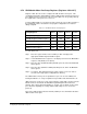


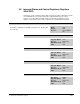
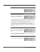
Table Of Contents
- S-3056-1 Distributed Power System SA3100 Drive Configuration and Programming Instruction Manual
- Important User Information
- Contents
- List of Figures
- List of Tables
- Chapter 1 Introduction
- Chapter 2 Configuring the UDC Module, Regulator Type, and Parameters
- 2.1 Adding a Universal Drive Controller (UDC) Module
- 2.2 Entering the Drive Parameters
- 2.3 Configuring the Vector with Constant Power Regulator
- 2.4 Configuring the Volts per Hertz (V/Hz) Regulator
- 2.5 Configuring Flex I/O
- 2.6 Generating Drive Parameter Files and Printing Drive Parameters
- Chapter 3 Configuring the UDC Module’s Registers
- 3.1 Register and Bit Reference Conventions Used in this Manual
- 3.2 Flex I/O Port Registers (Registers 0-23)
- 3.3 UDC/PMI Communication Status Registers (Registers 80-89/1080-1089)
- 3.4 Command Registers (Registers 100-199/1100-1199)
- 3.5 Feedback Registers (Registers 200-299/1200-1299)
- 3.6 Application Registers (Registers 300-599, Every Scan) (Registers 1300-1599, Every Nth Scan)
- 3.7 UDC Module Test I/O Registers (Registers 1000-1017)
- 3.8 Interrupt Status and Control Registers (Registers 2000-2047)
- Chapter 4 Application Programming for DPS Drive Control
- Chapter 5 On-Line Operation
- Appendix A SA3100 Vector Regulator Register Reference
- Appendix B SA3100 Volts / Hertz Regulator Register Reference
- Appendix C SA3100 Local Tunable Variables
- Appendix D Vector with Constant Power Regulator
- Appendix E Volts per Hertz (V/Hz) Regulator
- Appendix F Status of Data in the AutoMax Rack After a STOP_ALL Command or STOP_ALL Fault
- Appendix G Torque Overload Ratio Parameter Precautions
- Appendix H Default Carrier Frequency and Carrier Frequency Limit for Drive Horsepower Ranges
- Appendix I Vector with Constant Power Parameter Entry Example
- Index
Configuring the UDC Module’s Registers
3-53
3.7 UDC Module Test I/O Registers (Registers 1000-1017)
This view is used to configure the UDC module’s Test Switch Inputs Register and the
Meter Port Setup Registers.
3.7.1 UDC Module Test Switch Inputs Register (Register 1000)
This view is used to configure the register that displays the status of the test switches
and LED indicators on the UDC module. Writing to this register will not change the
state of the LEDs. The status of this register is retained during a Stop All.
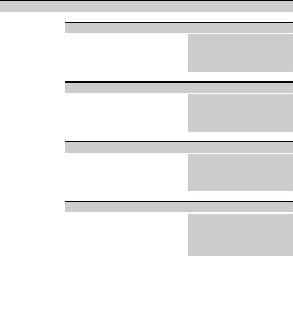
UDC Test Switch Inputs Register 1000
Pushbutton Input Bit 0
The Pushbutton Input bit is on when the
UDC’s pushbutton is pressed.
Hex Value: 0001H
Sug. Var. Name: UDC_PB@
Access: Read only
UDC Error Code: N/A
LED: N/A
Switch Up Input Bit 1
The Switch Up Input bit is on when the test
switch is in the up position.
Hex Value: 0002H
Sug. Var. Name: SWIT_UP@
Access: Read only
UDC Error Code: N/A
LED: N/A
Switch Down Input Bit 2
The Switch Down Input bit is on when the
test switch is in the up position.
Hex Value: 0004H
Sug. Var. Name: SWIT_DN@
Access: Read only
UDC Error Code: N/A
LED: N/A
Operating System OK LED Bit 8
The Operating System OK LED bit shows
the status of the Operating System OK LED
on the UDC module ( 0 = OFF; 1 = ON).
Hex Value: 0100H
Sug. Var. Name: N/A
Access: Read only
UDC Error Code: N/A
LED: OS OK on UDC
module