
Instruction Manual
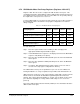


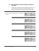
Table Of Contents
- S-3056-1 Distributed Power System SA3100 Drive Configuration and Programming Instruction Manual
- Important User Information
- Contents
- List of Figures
- List of Tables
- Chapter 1 Introduction
- Chapter 2 Configuring the UDC Module, Regulator Type, and Parameters
- 2.1 Adding a Universal Drive Controller (UDC) Module
- 2.2 Entering the Drive Parameters
- 2.3 Configuring the Vector with Constant Power Regulator
- 2.4 Configuring the Volts per Hertz (V/Hz) Regulator
- 2.5 Configuring Flex I/O
- 2.6 Generating Drive Parameter Files and Printing Drive Parameters
- Chapter 3 Configuring the UDC Module’s Registers
- 3.1 Register and Bit Reference Conventions Used in this Manual
- 3.2 Flex I/O Port Registers (Registers 0-23)
- 3.3 UDC/PMI Communication Status Registers (Registers 80-89/1080-1089)
- 3.4 Command Registers (Registers 100-199/1100-1199)
- 3.5 Feedback Registers (Registers 200-299/1200-1299)
- 3.6 Application Registers (Registers 300-599, Every Scan) (Registers 1300-1599, Every Nth Scan)
- 3.7 UDC Module Test I/O Registers (Registers 1000-1017)
- 3.8 Interrupt Status and Control Registers (Registers 2000-2047)
- Chapter 4 Application Programming for DPS Drive Control
- Chapter 5 On-Line Operation
- Appendix A SA3100 Vector Regulator Register Reference
- Appendix B SA3100 Volts / Hertz Regulator Register Reference
- Appendix C SA3100 Local Tunable Variables
- Appendix D Vector with Constant Power Regulator
- Appendix E Volts per Hertz (V/Hz) Regulator
- Appendix F Status of Data in the AutoMax Rack After a STOP_ALL Command or STOP_ALL Fault
- Appendix G Torque Overload Ratio Parameter Precautions
- Appendix H Default Carrier Frequency and Carrier Frequency Limit for Drive Horsepower Ranges
- Appendix I Vector with Constant Power Parameter Entry Example
- Index
Configuring the UDC Module’s Registers
3-55
3.7.2 UDC Module Meter Port Setup Registers (Registers 1000-1017)
Registers 1001-1017 are used to configure the UDC module’s meter ports. This
configuration determines what variables from the UDC module’s dual port memory are
to be displayed on the meter ports at the end of the UDC scan. At system power-up,
the output values of the ports are reset to zero.
To map a UDC variable to a specific meter port at power-up, refer to table 3.8 and use
the following procedure. Note that the setup register configurations are retained
during a Stop All.
For each meter port:
Step 1. Place the register number of the variable you wish to display in the
appropriate Variable Register Number register.
Step 2. If an individual bit of the register is to be displayed, enter it in the Bit Number
register as 100 (bit 00) to 115 (bit 15).
Step 3. Place the value (maximum 32767) that will represent +10V in the Maximum
Value register.
Step 4. Place the value (minimum -32768) that will represent -10V in the Minimum
Value register.
Step 5. Set register 1001 (Initiate Change in Setup) equal to a non-zero value to
store the new setup register configurations in memory.
The UDC module’s meter ports are updated once per scan once the UDC task is
running and CCLK is on. They are updated every 5 milliseconds when CCLK is off.
UDC meter ports can also be set up on-line using the “Setup UDC” selection from the
Monitor menu as described in the AutoMax Programming Executive instruction
manual. This setup is valid only until there is a power cycle, in which case the meter
ports default to outputting zero voltage and the UDC Setup screen is cleared on
power-up.
Refer to the UDC module instruction manual (S-3007) for more information about the
UDC module’s meter ports.
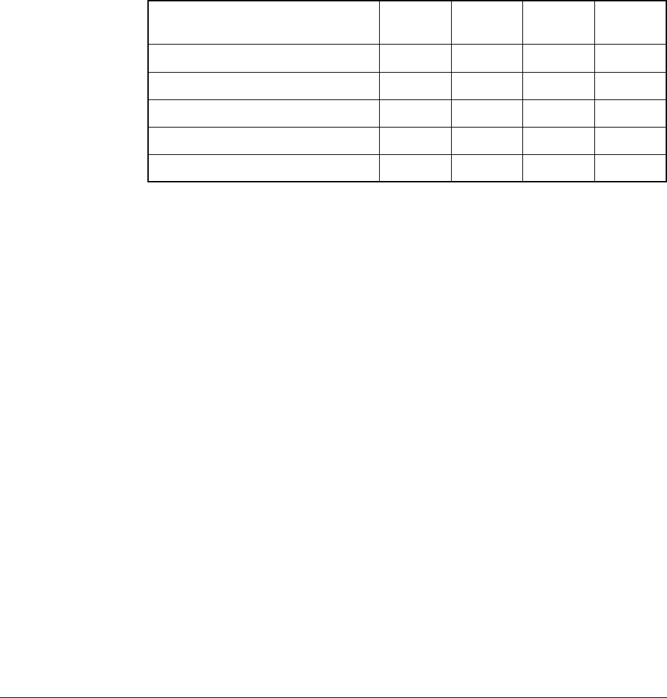
Table 3.8 – UDC Module Meter Port Setup Registers
UDC Module Meter Port
Setup Registers
Meter
Port 1
Meter
Port 2
Meter
Port 3
Meter
Port 4
Change Setup Register 1001 1001 1001 1001
Variable Register Number Register 1002 1006 1010 1014
Bit Number Register 1003 1007 1011 1015
Maximum Value Register 1004 1008 1012 1016
Minimum Value Register 1005 1009 1013 1017