
Instruction Manual
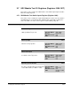
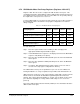
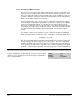


Table Of Contents
- S-3056-1 Distributed Power System SA3100 Drive Configuration and Programming Instruction Manual
- Important User Information
- Contents
- List of Figures
- List of Tables
- Chapter 1 Introduction
- Chapter 2 Configuring the UDC Module, Regulator Type, and Parameters
- 2.1 Adding a Universal Drive Controller (UDC) Module
- 2.2 Entering the Drive Parameters
- 2.3 Configuring the Vector with Constant Power Regulator
- 2.4 Configuring the Volts per Hertz (V/Hz) Regulator
- 2.5 Configuring Flex I/O
- 2.6 Generating Drive Parameter Files and Printing Drive Parameters
- Chapter 3 Configuring the UDC Module’s Registers
- 3.1 Register and Bit Reference Conventions Used in this Manual
- 3.2 Flex I/O Port Registers (Registers 0-23)
- 3.3 UDC/PMI Communication Status Registers (Registers 80-89/1080-1089)
- 3.4 Command Registers (Registers 100-199/1100-1199)
- 3.5 Feedback Registers (Registers 200-299/1200-1299)
- 3.6 Application Registers (Registers 300-599, Every Scan) (Registers 1300-1599, Every Nth Scan)
- 3.7 UDC Module Test I/O Registers (Registers 1000-1017)
- 3.8 Interrupt Status and Control Registers (Registers 2000-2047)
- Chapter 4 Application Programming for DPS Drive Control
- Chapter 5 On-Line Operation
- Appendix A SA3100 Vector Regulator Register Reference
- Appendix B SA3100 Volts / Hertz Regulator Register Reference
- Appendix C SA3100 Local Tunable Variables
- Appendix D Vector with Constant Power Regulator
- Appendix E Volts per Hertz (V/Hz) Regulator
- Appendix F Status of Data in the AutoMax Rack After a STOP_ALL Command or STOP_ALL Fault
- Appendix G Torque Overload Ratio Parameter Precautions
- Appendix H Default Carrier Frequency and Carrier Frequency Limit for Drive Horsepower Ranges
- Appendix I Vector with Constant Power Parameter Entry Example
- Index
3-56
SA3100 Drive Configuration and Programming
3.7.2.1 Resolution of Meter Port Data
For meter ports, the output values will be clamped at the outside (+/-10V) limits. Note
that if you select to display a data range that is narrower than the actual range of the
data, your output values will not change until the value returns to within the range you
selected to display. In other words, data is being updated at the rate described above,
but the actual output voltage may not change.
If the actual data being sent to the meter port is significantly smaller than the upper
and lower limits assigned by the programmer, the effective resolution of the 8-bit D/A
circuit (1 part in 255) will degrade. To calculate the step change indicated on the
meter port, calculate the sum or the absolute values of the upper and lower limits (the
entire range of possible values) assigned to the port. Then scale this number by 255
in order to determine the minimum step change that will cause the D/A output to
change.
For example, suppose the programmer sets the +10V and -10V limits at +4095 and -
4095, respectively, but the actual value varies only between +1024 and -1024. Then:
8190/255 = 32 counts
This means that although the actual data is being updated, the meter port output will
change only when the data changes by 32 or more counts. This level of granularity
might be acceptable if the range of the data were actually 8190 counts, but might not
be acceptable if the data range is only 4095 counts. If the programmer had assigned
the limits +/- 1024, the D/A output step change would be only 8 counts: 2048/255 = 8.
Initiate Change in Setup Register 1001
Set this register equal to a non-zero value to store the new setup
register configurations in UDC memory. You must use this register
whether you are changing the meter port setup via an application
task or via I/O Monitor.
Sug. Var. Name: N/A
Units: N/A
Range: N/A
Access: Read/Write