
Instruction Manual
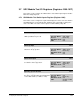
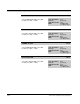
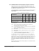


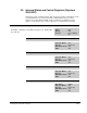
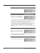
Table Of Contents
- S-3056-1 Distributed Power System SA3100 Drive Configuration and Programming Instruction Manual
- Important User Information
- Contents
- List of Figures
- List of Tables
- Chapter 1 Introduction
- Chapter 2 Configuring the UDC Module, Regulator Type, and Parameters
- 2.1 Adding a Universal Drive Controller (UDC) Module
- 2.2 Entering the Drive Parameters
- 2.3 Configuring the Vector with Constant Power Regulator
- 2.4 Configuring the Volts per Hertz (V/Hz) Regulator
- 2.5 Configuring Flex I/O
- 2.6 Generating Drive Parameter Files and Printing Drive Parameters
- Chapter 3 Configuring the UDC Module’s Registers
- 3.1 Register and Bit Reference Conventions Used in this Manual
- 3.2 Flex I/O Port Registers (Registers 0-23)
- 3.3 UDC/PMI Communication Status Registers (Registers 80-89/1080-1089)
- 3.4 Command Registers (Registers 100-199/1100-1199)
- 3.5 Feedback Registers (Registers 200-299/1200-1299)
- 3.6 Application Registers (Registers 300-599, Every Scan) (Registers 1300-1599, Every Nth Scan)
- 3.7 UDC Module Test I/O Registers (Registers 1000-1017)
- 3.8 Interrupt Status and Control Registers (Registers 2000-2047)
- Chapter 4 Application Programming for DPS Drive Control
- Chapter 5 On-Line Operation
- Appendix A SA3100 Vector Regulator Register Reference
- Appendix B SA3100 Volts / Hertz Regulator Register Reference
- Appendix C SA3100 Local Tunable Variables
- Appendix D Vector with Constant Power Regulator
- Appendix E Volts per Hertz (V/Hz) Regulator
- Appendix F Status of Data in the AutoMax Rack After a STOP_ALL Command or STOP_ALL Fault
- Appendix G Torque Overload Ratio Parameter Precautions
- Appendix H Default Carrier Frequency and Carrier Frequency Limit for Drive Horsepower Ranges
- Appendix I Vector with Constant Power Parameter Entry Example
- Index

Configuring the UDC Module’s Registers
3-61
3.8 Interrupt Status and Control Registers (Registers
2000-2047)
This view is used to configure registers that control the operation of interrupts to a task
on an AutoMax Processor in the rack and to enable CCLK in the rack. These
registers are used for Drive A and B. Only one UDC task should write to these
registers. Note that the status of these registers is not retained after a Stop All.
Interrupt Status Control Register 2000
The Interrupt Status Control register contains the following
information. Only bit 6 can be written to by the user. All other bits
are read only.
Sug. Var. Name: UDC_ISCR%
Units: N/A
Range: N/A
Access: See individual
bits
Interrupt Line Identification Bit 0
Hex Value: 0001H
Sug. Var. Name: N/A
Access: Read only
UDC Error Code: N/A
LED: N/A
Interrupt Line Identification Bit 1
Hex Value: 0002H
Sug. Var. Name: N/A
Access: Read only
UDC Error Code: N/A
LED: N/A
Interrupt Allocated Bit 2
Hex Value: 0004H
Sug. Var. Name: N/A
Access: Read only
UDC Error Code: N/A
LED: N/A
Interrupt Generated This Scan Bit 4
Hex Value: 0010H
Sug. Var. Name: N/A
Access: Read only
UDC Error Code: N/A
LED: N/A