
Manual

2-12
PMI Regulator
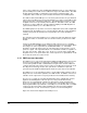
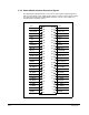
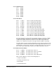
2.2.3 Power Module Interface Connector Signals
The 50-pin Power Module Interface connector is used for drive feedback signals as
well as for gate firing, power supply, and pre-charge contactor control signals. Figure
2.6 shows the pinout for the Power Module Interface connector. The signals are
described in the following sections.
+5V
50 49
+5V
DGND
48 47
DGND
I12V_RTN
46 45
ISO_12V
+24V
44 43
-15V
-15V
42 41
+15V
+15V
40 39
+5V
+5V
38 37
+5V
CVERIFY
36 35
PILOT
EE_CS
34 33
EE_SK
EE_IO
32 31
/CHARGE
AC_LINE
30 29
DESAT
GND_SHRT
28 27
POS_BUS
NEG_CAP
26 25
NEG_BUS
DGND
24 23
W_VOLTS
V_VOLTS
22 21
U_VOLTS
W_AMPS–
20 19
W_AMPS+
U_AMPS–
18 17
U_AMPS+
W_NEG–
16 15
W_POS–
V_NEG-
14 13
V_POS–
U_NEG–
12 11
U_POS–
W_NEG+
10 9
W_POS+
V_NEG+
87
V_POS+
U_NEG+
65
U_POS+
DGND
43
DGND
DGND
21
DGND
Figure 2.6 – PMI Connector Pinout