Distributed Power System SD3000 Drive Configuration and Programming Instruction Manual S-3006-1 r RELIANCE ELECTRIC Cl
The information in the user’s manual is subject to change without notice. ONLY QUALlFlED ELECTRICAL PERSONNEL FAMILIAR WITH THE CONSTRUCTION OPERATION OF THIS EQUIPMENT AND THE HAZARDS INVOLVED SHOULD INSTALL, ADJUST, OPERATE, OR SERVICE THIS EQUIPMENT. READ AND UNDERSTAND THIS MANUAL AND OTHER APPLICABLE MANUALS IN THEIR ENTIRETY BEFORE PROCEEDING. FAILURE TO OBSERVE THIS PRECAUTION COULD RESULT IN SEVERE BODILY INJURY OR LOSS OF LIFE.
Table of Contents 1 .O Introduction . . . . . .................................................................. 2.0 3.0 1 .1 Related Publications . . . . . . . . . . . . . . . . . . . . . . . . . . . . . . . . . . . . . . . . . . . . . . . . . . . . . . . . . . . . . . l-l Configuring the UDC Module, Regulator Type, and Parameters . . . . . . . . . . . . . . . . . . . . . . . . . 2-1 2.1 Adding a UDC Module . . . . . . . . . . . . . . . . . . . . . . . . . . . . . . . . . . . . . . . . . . . . . . .
Appendices Appendix A SD3000 Drive Register Reference . . . . . . . . . . . . . . . . . . . . . . . . . . . . . . . . . . . . . . . . . . . . . . . . . . . . . . . . A-l Appendix B SD3000 Local Tunable Variables . . . . . . . . . . . . . . . . . . . . . . . . . . . . . . . . . . . . . . . . . . . . . . . . . . . . . . . . . B-l Appendix C SD3000 Control Algorithm . . . . . . . . . . . . . . . . . . . . . . . . . . . . . . . . . . . . . . . . . . . . . . . . . . . . . . . . . . . . . . .
List of Figures Figure 2.1 - SD3000 Drive Parameter Entry Screen . . . . . . . . . . . . . . . . . . . . . . . . . . . . . . . . . . . . . . . . . . . . . . 2-3 Figure 2.2 - Armature Power Module Parameter Entry Screen . . . . . . . . . . . . . . . . . . . . . . . . . . . . . . . . . . . . . Figure 2.3 - l-Phase Field Power Module Parameter Entry Screen . . . . . . . . . . . . . . . . . . . . . . . . . . . . . . . . . 2-4 2-6 Figure 2.
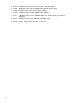
1 .0 INTRODUCTlON The products described in this manual are manufactured or distributed by Reliance Electric Industrial Company.
1-2 l S-3007 Distributed Power System Universal Drive Controller Module l S-3008 Distributed Power System SD3000 Power Module Interface Rack l S-3009 Distributed Power System Fiber-Optic Cabling l S-3010 Distributed Power System SD3000 Power Modules l S-3011 Distributed Power System SD3000 Diagnostics, Troubleshooting, and Startup Guidelines l S-3012 Distributed Power System SD3000 Information Guide l J2-3078 AutoMax Programming Executive Version 3.
2.0 CONFIGURING THE UDC MODULE, REGULATOR TYPE, AND PARAMETERS ONLY QUALIFIED ELECTRICAL PERSONNEL FAMILIAR WITH THE CONSTRUCTION AND OPERATION OF THIS EQUIPMENT AND THE HAZARDS INVOLVED SHOULD INSTALL, ADJUST, OPERATE, OR SERVICE THIS EQUIPMENT. READ AND UNDERSTAND THIS MANUAL AND OTHER APPLICABLE MANUALS IN THEIR ENTIRETY BEFORE PROCEEDING, FAILURE TO OBSERVE THIS PRECAUTION COULD RESULT IN SEVERE BODILY INJURY OR LOSS OF LIFE.
2.1.1 Rules for Configuring/Selecting Drives for the UDC Module 1 . Both A and B drives do not have to be used. (You can configure only one.) 2. Your A/B drive type combination is restricted only if you select either an SD3000 (12-Pulse) drive or an SF3000 drive for either drive A or drive B. For these products, you are restricted to the drive type combinations shown in the table below. All other drive type combinations are allowed. If you choose for Drive A. . . 2.2 Then your choices for Drive B are. .
l M/N 61 C351 2-Channel Analog Current Input/Output Rail l M/N 61 C365 4-Channel Analog Current Output Rail l M/N 61C366 4-Channel Analog Voltage Output Rail Click OK and the device will be added to the screen. If you are adding a digital I/O rail, you will need to configure the I/O modules that the rail contains. Double-click the rail to display the expanded digital I/O rail screen. To add an l/O module, select the module’s slot by moving the cursor to it and clicking it.
2.2.1 Armature Power Module Data Screen The Armature Power Module Data Screen allows you to enter specific information about the Power Module and motor to be used in your application. See figure 2.2. r UDC Drive 0 0 0 1 Drive B I q Armature Power Module Used AC tine Voltage (Volts RMS): 11 m Speed Feedback Data Meter Port Selection volts pq Amps piq Limit (%) 11501 Figure 2.
Armature Power Module Rating Selections You can enter Power Module ratings either manually or automatically through the W/D list. l W/D List You can choose from a list of wiring diagrams (W/D list) and have the specified default Power Module values entered in automatically. Appendix E lists these values. . D-C Volts Enter the maximum output voltage the Power Module will produce. The maximum allowable voltage is A-C line voltage plus 35%.
This value is also used to scale the current feedback and may range from 100 to 400%. The maximum amps produced by the Power Module can be calculated from the following equation: Maximum Amps* Produced = Amps x Maximum Current Limit by the Power Module 100 * Must be less than the Power Module’s output rating or 8000 amps (maximum). 2.2.
D-C Amps Enter the Field Power Module’s D-C Amps output value which can range from 1 to 100 Amps. There is no default value. This value is found on the Power Module’s nameplate and is used to scale field current feedback. Motor Field Ratina Selections Hot Amps There is no default value. This is the current that will be generated by the field power supply when current reference is at maximum. This value is found on the motor’s nameplate and can range from 0.01 to 99.99 Amps.
Figure 2.4 - Speed Feedback Parameter Entry Screen With No Feedback Device Selected Figure 2.
r0 Speed Feedback Type 0 No Speed Feedback view 0 0 Armature PM Data 0 Meter Port Selection Resolver @ Analog Tach Field PM Data Resolver Type @ None 0 xl 0 x2 0 x5 Figure 2.6 - Speed Feedback Parameter Entry Screen With An Analog Tachometer Selected Speed Feedback Tvpe Selections I WARNING THE USER MUST ENSURE THAT THE CORRECT FEEDBACK TYPE HAS BEEN SELECTED DURING CONFIGURATION.
Speed Safety Data Selections l Motor Base Speed (RPM) Enter the motor’s base speed. This value is the motor’s top operating speed under full field and is the speed when field weakening begins. This value is found on the motor’s nameplate and can range from 0 to 3600 RPM. l Over Speed Trip (RPM) Enter the overspeed trip point. This is the limit to be used for overspeed detection and can range from 0 to 5000 RPM. When an analog tachometer is used, this value is used to scale the analog voltage into RPM.
Figure 2.8 shows the values that can be displayed on the PMI meter ports. These values are described in detail in chapter 3. You must enter a Minimum Value and a Maximum Value for each selection except for those marked as Port Not Used. The Minimum Value is the value at which to output -1 0V The Maximum Value is the value at which to output + 1 OV. The system software then places the units per volt on the screen based on the Minimum/Maximum Values. The Minimum Value must not be less than -32768.
PMI meter ports can also be set up on-line using the “Setup UDC” selection from the Monitor menu as described in the AutoMax Programming Executive instruction manual. If the meter ports are set up during parameter entry, the information is loaded onto the UDC module in the AutoMax rack along with all other parameter data. The meter port setup can then be changed on-line under “Setup UDC”, but this method would not actually write over the PMI meter port setup that was loaded to the rack.
3.0 CONFIGURING THE UDC MODULE’S REGISTERS ONLY QUALIFIED ELECTRICAL PERSONNEL FAMILIAR WITH THE CONSTRUCTION AND OPERATION OF THIS EQUIPMENT AND THE HAZARDS INVOLVED SHOULD INSTALL, ADJUST, OPERATE, OR SERVICE THIS EQUIPMENT. READ AND UNDERSTAND THIS MANUAL AND OTHER APPLICABLE MANUALS IN THEIR ENTIRETY BEFORE PROCEEDING. FAILURE TO OBSERVE THIS PRECAUTION COULD RESULT IN SEVERE BODILY INJURY OR LOSS OF LIFE.
l The Application Registers Updated Every Nth Scan view is used to configure the application registers that are used for the passing of application-specific control and status data between an AutoMax Processor and the UDC module on every Nth scan, where “N” is defined in register 2001. This register range is shared by drive A and drive B. l The UDC Module Test I/O Register view is used to configure the register that displays the status of the UDC module’s test switches and LED indicators.
Table 3.
3.1 Rail I/O Port Registers (Registers O-23) The Rail I/O Port 0 and Port 1 views are used to assign variable names to the rail ports on the PMI. If you have no hardware attached to these ports, you do not configure these registers. All of the Rail data for PMI A and PMI B is combined into one section of the dual port memory. Refer to Table 3.3. Note that the usage of each register is a function of what type of Rail is configured.
Table 3.4 - Fault Register and Check Bit Fault Counter Register Usage for a Digital l/O Rail or 4-Output Analog Rail Module Bit 8: No device plugged into a configured port Bit 9: Bad ID code: device other than a rail is plugged into the port Bit IO: Bad rail communication check bits received Table 3.
Table 3.
80/1 080 UDC Module Ports A/B Status Register (Continued) Bit: 1 Hex Value: 0002H Sug. Var. Name: N/A Range: N/A Access: Read only UDC Error Code: N/A LED: N/A Description: The No End of Frame Status Received bit is set if the USC does not report an End of Frame condition when the receive interrupt is generated. Bit: 2 Hex Value: 0004H Sug. Var.
80/1 080 UDC Module Ports A/B Status Register (Continued) Bit: 6 Hex Value: 0040H Sug. Var. Name: N/A Range: N/A Access: Read only UDC Error Code: N/A LED: N/A Description: The CCLK Communication Synchronization Error bit is set when two or more CCLK counter ticks occur and no message is received. Bit: 7 Hex Value: 0080H Sug. Var.
80/1 080 UDC Module Ports A/B Status Register (Continued) Bit: 11 Hex Value: 0800H Sug. Var. Name: N/A Range: N/A Access: Read only UDC Error Code: N/A LED: N/A Description: The Invalid PMI Operating System Header bit is set if the UDC module cannot locate a valid PMI operating system header when attempting to load an operating system to a PMI.
84/1 084 PMI A/B Status Register The PMI A/B Status register contains bits which describe any errors or warnings reported by the PMI related to UDC/PMI communication on PMI A and PMI B. These bits are latched when set and will remain set until a fault reset or warning reset is issued. Bit: 0 Hex Value: 0001 H Sug. Var.
84/1 084 PMI A/B Status Register (Continued) Bit: 5 Hex Value: 0020H Sug. Var. Name: N/A Range: N/A Access: Read only UDC Error Code: N/A LED: N/A Description: The Transmitter Underrun bit is set when the USC reports a transmit first-in, first-out underrun. Bit: 6 Hex Value: 0040H Sug. Var. Name: N/A Range: N/A Access: Read only UDC Error Code: N/A LED: N/A Description: The CCLK Communication Synchronization Error bit is set when two or more CCLK counter ticks occur and no message is received.
84/1 084 PMI A/B Status Register (Continued) Bit: 13 Hex Value: 2000H Sug. Var. Name: N/A Range: N/A Access: Read only UDC Error Code: N/A LED: N/A Description: The Insufficient PMI Memory to Load the PMI Operating System bit is set by the PMI if there is insufficient memory for loading the operating system. This condition will cause the loading of the PMI operating system to fail; however, the UDC module and the PMI will continue to retry loading the PMI operating system. Bit: 14 Hex Value: 4000H Sug.
87/1087 PMI A/B Format Error Count Register Hex Value: N/A Sug. Var. Name: N/A Range: N/A Access: Read only UDC Error Code: N/A LED: N/A Description: This register contains the number of messages with format errors received by the Drive A and Drive B PMls. 88/1 088 UDC Module Potts A/B Fiber-Optic Link Status Register Hex Value: N/A Sug. Var. Name: N/A Range: N/A Access: Read only UDC Error Code: N/A LED: N/A Description: This register indicates the current operating state of fiber-optic links A and B.
3.3 Command Registers (Registers 100/1 99/1 100-1199) The Command Registers view is used to configure command registers. These registers are used for command data sent to the PMI by the UDC module at the end of every scan of the UDC Processor. Note that the bits in these registers (except bit 15 in register 100/1 100) are used to command action only and do not indicate the status of the action commanded. The feedback registers (registers 200/1 200 to 299/1 299) are provided for this purpose.
100/1 100 Drive Control Register (Continued) Bit: 3 Hex Value: 0008H Sug. Var. Name: CML_ATR@ Range: N/A Access: Read/Write UDC Error Code: N/A LED: N/A Description: The Armature Alpha Test Reverse bit is set to select the reverse bridge for the armature alpha test. Note that bit 2 must also be set to enable the test. The firing angle value is entered into the Armature Test Angle register 102/1 102 (CML_ALPHA%). If this bit is not set, the forward bridge will be tested.
1 00/1 100 Drive Control Register (Continued) Bit: 7 Hex Value: 0080H Sug. Var. Name: FML_ATR@ Range: N/A Access: Read/Write UDC Error Code: N/A LED: N/A Description: The Field Alpha Test Polarity bit is set to select the reverse bridge for the field alpha test. Bit 6 must also be set. The firing angle value is entered into the Field Test Angle register 104/1 104 (FLD_ALPHA%). This test is for the single phase field only. If this bit is not set the forward bridge will be tested.
100/1 100 Drive Control Register (Continued) Bit: 15 Hex Value: 8000H Sug. Var. Name: UDC_RUN@ Range: N/A Access: Read Only UDC Error Code: N/A LED: N/A Description: The UDC Task Running bit is a status bit that indicates that the UDC task is running. This bit is used by the PMI Processor to prevent the minor loop from running if the UDC task is not running. This bit must NOT be written to by the user. This is a status bit that is written to by the operating system.
101/1 101 I/O Control Register (Continued) Bit: 6 Hex Value: 0040H Sug. Var. Name: RES_CAL@ Range: N/A Access: Read/Write UDC Error Code: N/A LED: N/A Description: The Enable Resolver Calibration bit is set to start the test that determines the resolver’s balance value. This value will be stored in the pre-defined local tunable RES_BAL%. This bit is edge-sensitive. The test will turn off if the bit is turned off. Note that this calibration test should only be executed at one-half base speed.
101 /1 101 I/O Control Register (Continued) Bit: 15 Hex Value: 8000H Sug. Var, Name: UDC_LB@ Range: N/A Access: Read/Write UDC Error Code: N/A LED: N/A Description: The UDC Module External Loopback bit is set to enable the external loopback test on the UDC module’s fiber-optic ports. Register 101, bit 15 controls the COMM A test while register 1101, bit 15 controls the COMM B test. Note that this bit must be set to 0 before the loopback connector is removed from the UDC module’s fiber-optic ports.
104/1 104 Field Test Angie Register Hex Value: N/A Sug. Var. Name: FML_ALPHA% Range: 5 to 180 Access: Read/Write UDC Error Code: N/A LED: N/A Description: The value in the Field Test Angle register is the firing angle for the field alpha test. Firing angles can range from 180” (full off) to 5” (full on). Any value outside of this range is internally clamped to be within the limits. Note that the default value is 0 and the motor’s field must be disconnected for the test to execute.
3.4 Feedback Registers (Registers 200-299, 1200-1 299) The Feedback Registers view is used to configure the feedback registers that display the current status of the drive. These registers are updated by the PMI Processor and sent to the UDC module over the fiber-optic link before every scan of the UDC task. The status of these registers is retained after a Stop All. 200/1 200 Drive Status Register These bits indicate the current state of the drive.
200/1 200 Drive Status Register (Continued) Bit: 4 Hex Value: 001 OH Sug. Var. Name: FML_ON@ Range: N/A Access: Read Only UDC Error Code: N/A LED: N/A Description: The Field Regulator On bit set whenever the field regulator loop is executing/enabled. (See register 100/1 100, bit 4). When the request for the function is turned off, this bit will be turned Off. Bit: 5 Hex Value: 0020H Sug. Var.
200/1 200 Drive Status Register (Continued) Bit: 10 Hex Value: 0400H Sug. Var. Name: PH_ABC@ Range: N/A Access: Read Only UDC Error Code: N/A LED: N/A Description: The A-C Line Phase ABC bit is equal to one when the A-C line is phased ABC (181, 182, 183). If needed, the application program may test this bit to determine the A-C line phasing. This bit is equal to zero when the A-C line is phased ACB. Bit 11 is set equal to one when the phasing has been detected.
201 /1 201 I/O Status Register These bits indicate the current state of the inputs on the Resolver & Drive I/O module. Bit: 0 Hex Value: 0001 H Sug. Var. Name: RPI@ Range: N/A Access: Read Only UDC Error Code: N/A LED: RPI on the Resolver & Drive I/O module Description: The Run Permissive Input bit reflects the status of the run permissive input signal connected to pin A on the DRIVE I/O connector. When the signal is present, this bit is set.
201 /1 201 I/O Status Register (Continued) Bit: 5 Hex Value: 0020H Sug. Var. Name: AUX_IN5@ Range: N/A Access: Read Only UDC Error Code: N/A LED: AUX IN5 on the Resolver & Drive I/O module Description: The Auxiliary Input 5 bit reflects the status of 115 VAC auxiliary input 5 on the Resolver & Drive l/O module. When the input signal is present, this bit is on. Bit: 6 Hex Value: 0040H Sug. Var.
202/1 202 Drive Fault Register The bits in the Drive Fault register indicate the cause of a drive shutdown. The bits in this register are latched until they are reset by setting the Fault Reset bit (bit 8) of the Drive Control register (100/1 100). After turning the Fault Reset bit on, the drive may be re-started after turning the command bits off and then back on again. If the fault conditions still exist, the identifying bit in this register will immediately be set again.
202/1 202 Drive Fault Register (Continued) Btt: 6 Hex Value: 0040H Sug. Var. Name: FLT_FLD@ Range: N/A Access: Read Only UDC Error Code: 1006 LED: PM. FLT on the PMI Processor module Description: The Field Loss Fault bit will be set when: l 0 The field current feedback value is less than the Field Loss Trip Point parameter value entered during configuration for 5 times the electrical time constant of the field. This assumes FLD_RUN@ (register 100/1 100, bit 4) has been turned on.
202/1 202 Drive Fault Register (Continued) Bit: 10 Hex Value: 0400H Sug. Var. Name: FLT_OSP@ Range: N/A Access: Read Only UDC Error Code: 1010 LED: EXT FLT on the PMI Processor module Description: The Overspeed Fault bit is set when the motor’s velocity exceeds the value entered as the Over Speed Trip (RPM) configuration parameter. This bit is not used if the No Speed Feedback option is chosen as a configuration parameter. Bit: 11 Hex Value: 0800H Sug. Var.
202/1 202 Drive Fault Register (Continued) Bit: 15 Hex Value: 8 0 0 0 H Sug. Var. Name: FLT_COM@ Range: N/A Access: Read Only UDC Error Code: 1015 LED: N/A Description: The Communication Lost Fault bit is set when the fiber-optic communication between the PMI Processor and the UDC module is lost due to two consecutive communication errors of any type. This bit is set only after communication between the PMI Processor and the UDC module has been established. Refer to section 4.2.
203/1 203 Drive Warning Register (Continued) Bit: 3 Hex Value: 0008H Sug. Var. Name: WRN_SYN@ Range: N/A Access: Read Only UDC Error Code: N/A LED: N/A Description: The Synchronization Loss Fault Avoided bit is set when the system continues to operate through a temporary loss of A-C line voltage. Refer to register 202/1 202, bit 3 for more information. Bit: 4 Hex Value: 001 OH Sug. Var.
203/1 203 Drive Warning Register (Continued) Bit: 14 Hex Value: 4000H Sug. Var. Name: WRN_CLK@ Range: N/A Access: Read Only UDC Error Code: N/A LED: N/A Description: The CCLK Synchronized in PMI Warning bit is set when the CCLK counters in the PMI Processor and the UDC module are momentarily not synchronized. Bit: 15 Hex Value: 8000H Sug. Var.
204/1 204 SGR Diagnostic Register (Continued) Bit: 3 Hex Value: 0008H Sug. Var. Name: SCR_04@ Range: N/A Access: Read Only UDG Error Code: N/A LED: N/A Description: SCR 4 Fault (Forward Bridge) Bit: 4 Hex Value: 001 OH Sug. Var. Name: SCR_05@ Range: N/A Access: Read Only UDG Error Code: N/A LED: N/A Description: SCR 5 Fault (Forward Bridge) Bit: 5 Hex Value: 0020H Sug. Var.
204/1 204 SCR Diagnostic Register (Continued) Bit: 10 Hex Value: 0400H Sug. Var. Name: SCR_15@ Range: N/A Access: Read Only UDC Error Code: N/A LED: N/A Description: SCR 15 Fault (Reverse Bridge) Blt: 11 Hex Value: 0800H Sug. Var. Name: SCR_16@ Range: N/A Access: Read Only UDC Error Code: N/A LED: N/A Description: SCR 16 Fault (Reverse Bridge) 205/1 205 Interlock Register Interlock tests are executed whenever bits O-7 of register 100/1 100 are set.
205/1 205 Interlock Register (Continued) Bit: 2 Hex Value: 0004H Sug. Var. Name: WCI_GAN@ Range: N/A Access: Read Only UDC Error Code: N/A LED: N/A Description: The CML Gains Not Loaded bit is set if the armature gains are zero, i.e., have not been auto-tuned for, or if a UDC task containing the pre-defined gain variables has not been loaded. Bit: 3 Hex Value: 0008H Sug. Var.
205/1205 Interlock Register (Continued) Bit: 7 Hex Value: 0080H Sug. Var. Name: WCI_MCR@ Range: N/A Access: Read Only UDC Error Code: N/A LED: N/A Description: The M-Contactor Not Closed bit is set if the M-Contactor did not close at the expected time. Bit: 8 Hex Value: 01 OOH Sug. Var.
206/1 206 A-C Line Voltage Feedback Register Hex Value: N/A Sug. Var. Name: AC_VRMS% (RMS Volts) Range: N/A Access: Read Only UDC Error Code: N/A LED: N/A Description: The A-C Line Voltage Feedback register displays the measured A-C RMS line voltage. A value of 1 is equal to 1 volt. 207/1207 Current Minor Loop Feedback Register Hex Value: N/A Sug. Var.
21 1/121 1 Field Minor Loop Feedback Register Hex Value: N/A Sug. Var. Name: FML_FB% Range: -32768 to +32767 Access: Read Only UDC Error Code: N/A LED: N/A Description: The Field Minor Loop Feedback register displays the measured field current (DC Amps) in counts. A value of 4095 is equal to 100% of the Motor Field Hot Amps value in the parameter entry screen. 212/1 212 Field Current Feedback Register Hex Value: N/A Sug. Var.
3.5 Application Registers (Registers 300-599, (Registers 13004599, Every Nth Scan) Every Scan) The application registers are used to pass application-specific data between an AutoMax Processor and the UDC module. Memory is allocated for a maximum of 600 application registers which are used by both tasks (A and B). There are 300 registers that can be used every scan (registers 300-599) and 300 registers that can be used every Nth scan (registers 13004599). “N” is defined in register 2001.
.: 8 N I --------v----e--- if $5 5 ---e--s---------- Figure 3.
The following data types can be defined in the application register area: boolean (bit), integer (16 bits), double integer (32 bits), and real (32 bits). Because of the way in which read and write operations occur in the UDC dual port memory, however, the programmer must assign boolean variables carefully within pairs of 16-bit registers. The UDC operating system generally operates on the amount of memory called for by the data type, e.g.
1000 UDC Test Switch Inputs Register (Continued) Bit: 2 Hex Value: 0004H Sug. Var. Name: SWIT_DN@ Range: N/A Access: Read only UDC Error Code: N/A LED: N/A Description: The Switch Down Input bit is on when the switch is in the down position. Bit: 8 Hex Value: 01 00H Sug. Var. Name: N/A Range: N/A Access: Read only UDC Error Code: N/A LED: OS OK on the UDC module Description: Status of the Operating System OK LED on the UDC module (0 = Off; 1 = On). Bit: 9 Hex Value: 0200H Sug. Var.
3.6.2 UDC Module Meter Port Setup Registers (Registers 10014017) Registers 1001-l 017 are used to configure the UDC module’s meter ports. This configuration determines what variables from the UDC module’s dual port memory are to be displayed on the meter ports at the end of the UDC scan. At system power-up, the output values of the ports are reset to zero. To map a UDC variable to a specific meter port at power-up, refer to table 3.7 and use the following procedure.
This means that although the actual data is being updated, the meter port output will change only when the data changes by 32 or more counts. This level of granularity might be acceptable if the range of the data were actually 8190 counts, but might not be acceptable if the data range is only 4095 counts. If the programmer had assigned the limits +/-1024, the D/A output step change would be only 8 counts: 2048/255 = 8. 1001 Initiate Change in Setup Register Hex Value: N/A Sug. Var.
Meter Port 1 1002 UDC Module Meter Port 1 Register Number Register Hex Value: N/A Sug. Var. Name: N/A Range: N/A Access: Read/Write UDC Error Code: N/A LED: N/A Description: UDC register number (o-2044) to be mapped to meter port 1. 1003 UDC Module Meter Port 1 Bit Number Register Hex Value: N/A Sug. Var. Name: N/A Range: N/A Access: Read/Write UDC Error Code: N/A LED: N/A Description: Bit number of the UDC register specified in register 1002 that is to be mapped to port 1.
Meter Port 2 1008 UDC Module Meter Port 2 Register Number Register Hex Value: N/A Sug. Var. Name: N/A Range: N/A Access: Read/Write UDC Error Code: N/A LED: N/A Description: UDC register number (o-2044) to be mapped to meter port 2. 1007 UDC Module Meter Port 2 Bit Number Register Hex Value: N/A Sug. Var. Name: N/A Range: N/A Access: Read/Write UDC Error Code: N/A LED: N/A Description: Bit number of the UDC register specified in register 1006 that is to be mapped to port 2.
Meter Port 3 1010 UDC Module Meter Port 3 Register Number Register Hex Value: N/A Sug. Var. Name: N/A Range: N/A Access: Read/Write UDC Error Code: N/A LED: N/A Description: UDC register number (o-2044) to be mapped to meter port 3. 1011 UDC Module Meter Port 3 Bit Number Register Hex Value: N/A Sug. Var. Name: N/A Range: N/A Access: Read/Write UDC Error Code: N/A LED: N/A Description: Bit number of the UDC register specified in register 1010 that is to be mapped to port 3.
Meter Port 4 1014 UDG Module Meter Port 4 Register Number Register Hex Value: N/A Sug. Var. Name: N/A Range: N/A Access: Read/Write UDG Error Code: N/A LED: N/A Description: UDC register number (o-2044) to be mapped to meter port 4. 1015 UDG Module Meter Port 4 Bit Number Register Hex Value: N/A Sug. Var. Name: N/A Range: N/A Access: Read/Write UDG Error Code: N/A LED: N/A Description: Bit number of the UDC register specified in register 1014 that is to be mapped to port 4.
3.7 Interrupt Status and Control Registers (Registers 2000-2047) This view is used to configure registers that control the operation of interrupts to a task on an AutoMax Processor in the rack and to enable CCLK in the rack. These registers are used for Drive A and B. Only one UDC task should write to these registers. Note that the status of these registers is not retained after a Stop All. 2000 Interrupt Status Control Register Hex Value: N/A Sug. Var.
2000 Interrupt Status Control Register (Continued) Bit: 5 Hex Value: 0020H Sug. Var. Name: N/A Range: N/A Access: Read only UDC Error Code: N/A LED: N/A Description: CCLK Counting. Bit: 6 Hex Value: 0040H Sug. Var. Name: N/A Range: N/A Access: Read/Write UDC Error Code: N/A LED: N/A Description: Enable CCLK on the Multibus Backplane - CCLK must be enabled in the rack for the UDC module to execute its task(s) and communicate synchronously with the PMI. Only one module per rack should enable CCLK.
4.0 APPLICATION PROGRAMMING FOR DPS DRIVE CONTROL ONLY QUALIFIED ELECTRICAL PERSONNEL FAMILIAR WITH THE CONSTRUCTION AND OPERATION OF THIS EQUIPMENT AND THE HAZARDS INVOLVED SHOULD INSTALL, ADJUST, OPERATE, OR SERVICE THIS EQUIPMENT. READ AND UNDERSTAND THIS MANUAL AND OTHER APPLICABLE MANUALS IN THEIR ENTIRETY BEFORE PROCEEDING. FAILURE TO OBSERVE THIS PRECAUTION COULD RESULT IN SEVERE BODILY INJURY OR LOSS OF LIFE.
Any UDC dual port register that is to be used in a UDC task must be defined as COMMON in the task. Recall that UDC dual port memory registers are either reserved for a specific use such as rail data, or available for application-specific purposes to the programmer.
4.2.1 Typical Structure of a UDC Task The typical structure of a UDC task is described below. The first part of the task, described in steps 1 to 4 below, is considered task initialization. This part of the task will only run on the initial scan of the task or on any subsequent restart. 1. Local and common variable definitions This section of the task defines names for values internal to the task (LOCALS) and all UDC dual port memory registers used in the task (COMMONS). 2.
Note that, unlike Control Block tasks on AutoMax Processors, UDC tasks cannot run on a hardware or software event basis. The EVENT parameter cannot be specified in the SCAN-LOOP block in UDC tasks. This means that there is no timeout for execution of the UDC tasks. If the UDC task is scanned to the SCAN-LOOP block and CCLK is not on, the task will simply wait without timing out. Note that no other control blocks are permitted before the SCAN-LOOP block.
The rate at which the CALC_RISE block parameter counts up and down is calculated so that a step from 100% to LIM_BAR will turn on the OVERLOAD in TRIP-TIME seconds. If current feedback steps from 100% to a value less than current limit, it will take longer to detect the overload. If I_FDBK is stepped from zero to LIM-BAR, the block will take approximately four times the value of TRIP-TIME to detect the overload. UL 508C section 56.1.
3 . Enter the desired value into the “CURRENT” field for each LOCAL statement. The programmer can choose to enter the desired values for any local tunables in the “CURRENT” field of the corresponding LOCAL statement or leave them unchanged. 4.2.3 UDC/PMI Task Communication Coordination between the two PMls running their respective PMI tasks (drives A and B) and the UDC module running the corresponding UDC tasks is managed through the command and feedback messages sent over the fiber-optic link.
To verify that communication between the UDC module and the PMI is resulting in up-to-date feedback data, it is recommended that the drive’s run permissive logic include the CCLK synchronized status bit (register 200/1200, bit 14, CCLK_OK@) and the communication lost fault bit (register 202/1202, bit 15, COM_FLT@) as shown below: I I Start Permissive Logic I I CCLK-OK@ : RUN-PERM@ COM-FLT@ RUN-PERM@ : L-------------J Refer to the individual bit descriptions in this manual for more information.
Figure 4.
4.3 AutoMax Processor Task and UDC Task Coordination Recall that all tasks running on AutoMax Processors have access to the UDC dual port registers, but that UDC tasks can only access those common variables that represent registers in their own dual port memory. Task coordination between the UDC module and the AutoMax Processor is generally handled through periodic hardware interrupts generated by the UDC module.
.E E 8 N I ----- m - - - - .-C E 8 NT Figure 4.
5.0 ON-LINE OPERATION ONLY QUALIFIED ELECTRICAL PERSONNEL FAMILIAR WITH THE CONSTRUCTION AND OPERATION OF THIS EQUIPMENT AND THE HAZARDS INVOLVED SHOULD INSTALL, ADJUST, OPERATE, OR SERVICE THIS EQUIPMENT. READ AND UNDERSTAND THIS MANUAL AND OTHER APPLICABLE MANUALS IN THEIR ENTIRETY BEFORE PROCEEDING. FAILURE TO OBSERVE THIS PRECAUTION COULD RESULT IN SEVERE BODILY INJURY OR LOSS OF LIFE.
5.3 Running, Stopping, and Deleting UDC Application Tasks WARNING UNDERSTAND THE APPLICATION BEFORE STARTING A TASK. OUTPUTS MAY CHANGE STATE, RESULTING IN MACHINE MOVEMENT. FAILURE TO OBSERVE THESE PRECAUTIONS COULD RESULT IN BODILY INJURY. WARNING IT IS THE RESPONSIBILITY OF THE USER TO ENSURE THAT THE APPLICATION PROCESS STOPS IN A SAFE MANNER WHEN THE APPLICATION TASKS STOP. FAILURE TO OBSERVE THESE PRECAUTIONS COULD RESULT IN BODILY INJURY.
Appendix A SD3000 Drive Register Reference REGISTER Registers MAP UDC-PMI COMMUNlCATION A/B 6011060 Function 0-23 Rail l/O port registers 24-79 System Use Only 80-89 UDC/PMI 90-99 System Use Only comm.
*Appendix A (Continued) FEEDBACK REGISTERS (Continued) 300-599 A/B 205/1205 Interlock Bit WCI_ILL@ 0 Multiple CML requests 1 Arm. parameters not loaded WCI_CNF@ 2 Arm, gains not loaded WCI_GAN@ 3 Arm. faults need to be reset WCI_FLT@ 4 Run permissive missing WCI_RPl@ 5 Arm. field not ready WCI_FNR@ WCI_FNA@ 6 Arm.
Appendix B SD3000 Local Tunable Variables Armature and Field Gain Variables With the exception of armature and field crossover frequency, armature and field current gain variable values can be generated automatically by using the armature and field ID commands, respectively, in register 100/1100. Crossover frequency for both the armature and the field must be entered by the user if the default (CURRENT parameter) is not acceptable. The STEP parameter for all the variables is always one (1).
Appendix B Continued l FML_WCO% - Field Minor Loop Crossover Frequency Default Current Value: 15 Low Limit: 0 High Limit: 75 Step: 1 The value in this variable selects the desired response of the field regulation loop. It is used by the field current regulation algorithm running on the PMI Processor to keep the CEMF value constant when operating above the base motor speed. It is scaled in radians per second.
Appendix B Continued Resolver Gain and Balance Variables The resolver gain and balance variable values are used to compensate for varying lengths of resolver wiring. The balance value can be generated automatically by commanding the resolver calibration test in register 101/1 101. The gain value will be generated automatically when the RES_GAN% variable is equal to zero, i.e., on power-up. Refer to the Power Module Interface Rack manual for more information on the calibration procedures.
Appendix B Continued Open SCR Diagnostic Variables The open SCR diagnostics are used to make certain that all SCRs in the Power Module are, on the average, carrying the same load. The current flow through each SCR is compared to the average current being supplied by the Power Module. If an SCR is not carrying its share of the load, that SCR or SCR pair in the case of a regenerative drive, will be identified in register 204/1204, and a warning will be reported in register 203/1 203.
Appendix B Continued The SCR diagnostic tunables are summarized below. The first step in the diagnostics is to update a running average of the current feedback over the last 12 SCR firings. The next step in the routine is to calculate the error as follows: Error = (Running-Average - Current Feedback) * 100 Running-Average If the calculated error is less than SCR_DBAND%, then the error is set to zero. Higher values in SCR_DBAND% can keep small errors from causing nuisance faults.
Appendix C SD3000 Control Algorithm Armature and field current regulation in SD3000 Drives is performed by the PMI Processor. Application tasks on the UDC module and AutoMax Processor are used to intiate auto-tuning, run and stop the current regulation algorithms, monitor the PMI Processor for warnings and faults, and coordinate with higher-level control tasks.
Appendix C SD3000 Armature Current Regulation Algorithm C-2
.------ ----- R - r c-3
Appendix C SD3000 Field Current Regulation Algorithm C-4
I 1 A i a,
Appendix D Status of Data in the AutoMax Rack after a STOP-ALL Command or STOP-ALL Fault AutoMax Processor LOCAL tunable variables LOCAL variables COMMON memory variables I/O variables (including UDC dual port memory) Input values, including: Feed back registers UDC/PMI communication status registers UDC Error Log info Output values, including: Command registers Application registers ISCR registers Scan-per-interrupt register Scans-per-interrupt counter Parameter configuration variables UDC test switch info
Appendix E Power Module Model Numbers and Parameter Default Values 230 VAC Line Voltage - S6 Drive Model Number HP (KW) D-C Output Volts D-C Output Amps CT Turns Ratio 30300-I s l-7.5 240 1 O-27 100:1 (1.5-7.5) 8-30 15-20 (11-l 5) 240 240 240 240 240 38 30-I 00 73 90-265 320-480 240 240 600 600 685-850 850-I 000 666 1250 0* 500: 1 1000:1 2000: 1 3860: 1 7770: 1 7770: 1 30300-RB 30301-1s 30301 -RE 30302-RE 30303-m 30304-RB 30304-RD 840.55.10 840.57.
Appendix E (Continued) 380 and 460 VAC Line Voltage - S6 Drive 1 Model Number 1 I I I I I I I I I I I I 30300-l s I D-C Output Volts 1 D-C Output Amps 1 CT Turns Ratio HP (Kw) 2-l 5 500 30300-SB 30301-1s 30301 -SE 30302-SE 30303-SC 5-20 (3.
Appendix E (Continued) 575 VAC Line Voltage - S6 Drive Model Number 30302-TE I I I I I 30303-TC 30304-TC 29676-7 29676-9 840.57.
Appendix F Armature Current Feedback Resolution Current feedback normally has between 12 and 13 bits of resolution. This resolution may be degraded if a Power Module is misapplied. The Programming Executive software will warn you if this can happen because of any parameter entry errors you make.The following explains how current feedback scaling is done and what you can do to avoid this problem.
Appendix F (Continued) To determine how low full load current can go before the gain will be limited, and resolution degraded, use the following equation: I_full_low_limit = CT / ( 10.2 * (I-limit + 75%)) Using the same CT ratio of 2000:1, the low limit of full load current is 87 amps.
Appendix G Drive Control Register Operating States The following table indicates which Drive Control register (100/1 100) commands can be executed at the same time. Armature Current (CML) Control Modes Idle (default) Alpha Test Forward Alpha Test Reverse I.D. Test Run Yes Yes Yes Yes no* Yes no no no no Yes no no no no I.D.
Appendix H Field Current Regulation Algorithm with Field Weakening Turned Off IField Current Regulation Algorithm FML-RUN@, FML-ON@ FML On/Off Sequence I FML-FB% FLD- -I MIN% FML-FIEF% \r Y v PROP_,NT m I I I I I ; I I I I - x e --)* D-Frlhwer y cBh’gd,Sge, SCR ’ e Gate: Module FML-FB AC-VRMS% F b Refer to register 100/l 100, bit 11 in chapter 3 for additional information.
Appendix I Instantaneous Overcurrent Trip Point The instantaneous overcurrent (IOC) trip point is a function of the maximum current limit value and the motor’s armature current as shown in the following equation: IOC Trip Point = Armature Amps x (Max Current Limit + 75%) When the maximum current limit value is equal to 150%, the upper limit of the IOC trip point is set at 225% of the motor’s armature current value.
Appendix J D-C Amp Rating Parameter Precautions Normally, the D-C Amp rating parameter is automatically filled in by the system after the user selects a Power Module part number from the list. However, if you are filling in your own values because you are using a Power Module that is not on the list, you must take the following precaution when filling in the D-C Amp rating parameter.
Technical Writing In ternal Use: Forward To,: Reliance Electric V*S Drives Technical Writing Group 24701 Euclid Ave. Cleveland, OH 44117 OIF # VW DRIVES DOCUMENTATION IMPROVEMENT FORM Document Number= Page Number(s): Comments: (Please give chapters, page numbers or specific paragraphs that the change will affect. Include markups from the document or attach additional pages if necessary.
TRAINING AND AUDIO/VISUAL PRODUCTS Reliance Electric offers a wide variety of Industrial Training courses for electricians, electronic technicians and engineers who are responsible for the installation, repair and maintenance of production equipment and systems. Professional quality A/V Programs are also available. These programs have been designed to provide years of efficient in-house training.
Reliance Electric / 24703 Euclid Avenue / Cleveland, Ohio 44117 / (216) 266-7000 r RELIANCE ELECTRIC Printed in USA.