Distributed Power System SD3000/SF3000 Parallel Gate Amplifier System Instruction Manual S-3045-2
Throughout this manual, the following notes are used to alert you to safety considerations: ! ATTENTION: Identifies information about practices or circumstances that can lead to personal injury or death, property damage, or economic loss. Important: Identifies information that is critical for successful application and understanding of the product.
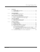
CONTENTS Chapter 1 Introduction 1.1 Standard Features ........................................................................................... 1-2 1.2 Related Hardware and Software ..................................................................... 1-2 1.3 Related Publications ........................................................................................ 1-4 Chapter 2 About the PGA Rack 2.1 PGA Rack Mechanical Description..................................................................
Appendix A Rack Specifications.................................................................................................. A-1 Appendix B Power Supply Module Specifications ....................................................................... B-1 Appendix C PGA Module Specifications...................................................................................... C-1 Appendix D PGA Maximum System Power Requirements .........................................................
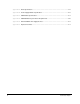
List of Figures Figure 1.1 – Four-Slot PGA Rack and Modules (Part No. 805401-7T) .................... 1-5 Figure 1.2 – Eight-Slot PGA Rack and Modules (Part No. 805401-9CC)................. 1-6 Figure 1.3 – PGA Parallel Motoring and Regenerating System Example ................ 1-7 Figure 3.1 – Power Supply Module Component Layout ........................................... 3-3 Figure 3.2 – Power Supply Module Functional Block Diagram................................. 3-4 Figure 4.
IV Parallel Gate Amplifier
List of Tables Table 1.1 – Parallel Gate Amplifier System Configurations ......................................1-3 Table 1.2 – DPS Documentation...............................................................................1-4 Table 5.1 – Input Power Connections .......................................................................5-7 Table 5.2 – Connection Sequence for Cable Assemblies 612436 and 612567........
VI Parallel Gate Amplifier
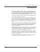
CHAPTER 1 Introduction The Parallel Gate Amplifier (PGA) system is used to amplify and distribute the gate pulse signals produced by the AutoMax™ Distributed Power System's DC Power Technology module. It can be used with multiple Reliance Power Modules or with certain other vendor Power Modules. Please contact Reliance regarding the suitability of other vendor Power Modules for use with the PGA system.
1.
Table 1.1 – Parallel Gate Amplifier System Configurations Reliance Part No.
1.3 Related Publications This manual provides a description of each component of the Parallel Gate Amplifier system as well as installation guidelines. Note that this instruction manual does not describe specific applications of the standard hardware. Additional information about using the Parallel Gate Amplifier as part of an AutoMax Distributed Power System is found in the instruction manuals, prints, and other documents shipped with each drive system.
Figure 1.1 – Four-Slot PGA Rack and Modules (Part No.
Figure 1.2 – Eight-Slot PGA Rack and Modules (Part No.
Figure 1.
1-8 Parallel Gate Amplifier
CHAPTER 2 About the PGA Rack The PGA rack provides the mechanical means for mounting the Power Supply module and the PGA modules. The following sections provide mechanical and electrical descriptions of the rack. 2.1 PGA Rack Mechanical Description The PGA rack consists of a sheet metal card-cage type enclosure and a backplane. The backplane contains a proprietary parallel bus with DIN-style connectors in each slot for the modules. The leftmost slot is provided for the Power Supply module.
2-2 Parallel Gate Amplifier
CHAPTER 3 About the PGA Power Supply Module Through its faceplate connectors, the PGA Power Supply module (B/M O-60055) provides the interface with the DC Power Technology module in the PMI rack. The Power Supply module provides the gate signals and the DC voltages necessary for the proper operation of the PGA modules through the backplane of the PGA rack. The following sections provide mechanical and electrical descriptions of the Power Supply module. Component layout is shown in figure 3.1.
3.2 PGA Power Supply Module Electrical Description The PGA Power Supply module includes an internal +28 VDC regulated power supply and a 28 volt to 5 volt DC-to-DC converter. The internal regulated supply requires a 115 VAC input. Its output provides the DC bus power for the six FET gate firing circuits on each PGA module. The internal regulated supply also powers the DC-to-DC converter, which in turn generates the +5 VDC output necessary for the six biasing networks on each PGA module.
TB1 TB2 Figure 3.
Figure 3.
CHAPTER 4 About the PGA Module The PGA module isolates and amplifies the gate signal pulses received from one of the two rack backplane channels, A or B. The type of PGA module used depends upon the channel it will access. An Output-A PGA module (B/M O-60056) receives its signals from channel A. An Output-B PGA module (B/M O-60071) receives its signals from channel B. The user must ensure that the correct type of PGA module is used for the channel desired.
The standard DC bus voltage is +28 VDC, but the PGA module is capable of handling DC bus voltages up to +100 VDC, if required by the application. Voltages greater than the standard +28 VDC must be provided by an externally mounted power supply, connected to the Power Supply module’s P/S 2 and COM faceplate terminals. See chapter 3. The PGA module has one internal fuse. The fuse is not user-serviceable. A blown fuse indicates that the PGA module has failed and must be replaced.
Power Module Parallel Gate Amplifier Gate Coupler Circuit Gate Driver #1 Gate Coupler Circuit Gate Driver #2 Gate Coupler Circuit Gate Driver #3 Gate Coupler Circuit Gate Driver #4 Gate Coupler Circuit Gate Driver #5 Gate Coupler Circuit Gate Driver #6 P1 Connector Shown (P2, P3, and P4 are identical to P1). Figure 4.
Figure 4.
CHAPTER 5 Installation Guidelines ! ATTENTION:Only qualified personnel familiar with the construction and operation of this equipment and the hazards involved should install, adjust, operate, or service this equipment. Read and understand this manual and other applicable manuals in their entirety before proceeding. ATTENTION:The modules in the Parallel Gate Amplifier rack contain static-sensitive components. Do not touch the module’s circuit board or the connectors on the back of the module.
5.2 Installing the PGA Rack The rack is designed to be panel-mounted using M6 or 1/4"-20 screws. The holes in the top flange have a keyhole shape and the lower holes are U-shaped to facilitate mounting. Refer to figure 5.1 (four-slot rack) or figure 5.2 (eight-slot rack) for mounting dimensions. Use the following guidelines when installing the PGA rack: 5-2 • Ensure that there is enough space for the rack, wiring, terminal strips, and other devices that must be mounted near the rack.
Figure 5.
Figure 5.
5.3 Grounding Considerations ! ATTENTION: Ungrounded equipment presents a shock hazard. The ground terminal on the power supply module and the grounding lug on the rack are not connected together. Connect both points to an external earth ground. The ground terminal on the Power Supply module and the grounding lug on the rack are not connected. Both points must be connected externally to earth ground and checked with an ohmmeter before power is applied.
5.4 Module Installation/Replacement Guidelines ! ATTENTION:Inserting or removing a module or its connecting cables may result in unexpected machine motion. Turn off power to the PGA rack before inserting or removing a module or its connecting cables. ATTENTION:The modules in the Parallel Gate Amplifier rack contain static-sensitive components. Do not touch the module's circuit board or the connector on the back of the module. When not in the rack, the module should be stored in an anti-static bag.
5.5.1 Connecting AC Input Power The 115 VAC Input terminals on the Power Supply module must be wired to the AC power source using twisted-pair wire. Refer to table 5.1 when connecting AC input power to the Power Supply module. Table 5.1 – Input Power Connections Wire Color Wire Label 115VAC Input Red AC Line High L1 White AC Line Neutral L2 Green Earth Ground NOTE: The PGA rack is shipped with the fan internally connected to the L1 and L2 terminals labeled "115 VAC OUTPUT TO FAN." 5.5.
The other end of each cable has a fifteen-pin female D-shell connector that mates with the faceplate connectors on the PGA Power Supply module. The forward gate signal cable should be connected to Input A and the reverse gate signal cable to Input B. Appendix F provides a list of the Power Supply module cables used with the PGA system. Note that the Power Supply cable length must not exceed 3.7 m (12 ft).
Table 5.2 – Connection Sequence for Cable Assemblies 612436 and 612567 Thyristor 1: Thyristor 2: Thyristor 3: Thyristor 4: Thyristor 5: Thyristor 6: Signal From D-Shell Connector Pin Wire Color To Gate Driver Plug Pin Gate 1 5 BRN 1 DC Bus 15 WHT/BRN 2 Gate 2 4 RED 3 DC Bus 14 WHT/RED 4 Gate 3 3 ORG 5 DC Bus 13 WHT/ORG 6 Gate 4 2 YEL 9 DC Bus 12 WHT/YEL 10 Gate 5 7 GRN 11 DC Bus 11 WHT/GRN 12 Gate 6 1 BLU 13 DC Bus 6 WHT/BLU 14 Figure 5.
Figure 5.
APPENDIX A Rack Specifications Ambient Conditions • Operating temperature: 0 to 40°C (32 to 104°F) ambient allowing for a maximum 20°C (36°F) temperature rise inside enclosure • Storage temperature: - 30 to 85°C (-22 to +185°F) • Humidity: 5 to 95% non-condensing Rack Dimensions Four-Slot Rack with Fan • Height: 290 mm (11.5 in) • Width: 180 mm (7.09 in) • Depth: 184 mm (7.25 in) Eight-Slot Rack with Fan • Height: 290 mm (11.5 in) • Width: 324 mm (12.75 in) • Depth: 184 mm (7.
A-2 Parallel Gate Amplifier
APPENDIX B Power Supply Module Specifications Ambient Conditions • Operating temperature: 0 to 40°C (32 to 104°F) ambient allowing for a maximum 20°C (36°F) temperature rise inside enclosure • Storage temperature: - 30 to 85°C (-22 to +185°F) • Humidity: 5 to 95%, non-condensing Maximum Module Power Dissipation • 30 W Dimensions • Height: 205 mm (8.063 in) • Width: 103.0 mm (4.055 in) • Depth: 178.8 mm (7.
DC Outputs 5 Volt supply: • Output voltage: 5V (+/- 1%): 0 - 2 A @ 60 °C • Line regulation: 0.2% (18V - 36V) • Load regulation: 1% (0 to full load) • Noise ripple: 75 mV • Efficiency: 78% • Overcurrent protection: Can sustain short circuit indefinitely • Overvoltage protection: Overvoltage clamping @ 6.2 - 6.5V • Protection: Fuse (not user-serviceable) 28 Volt supply: • Output voltage: 28V (+/- 5%):0 - 5A @ 40°C, 0 - 4.4A @ 50°C, 0 - 3.7A @ 60°C • Line regulation: 0.
APPENDIX C PGA Module Specifications Ambient Conditions • Operating temperature: 0 to 40°C (32 to 104°F) ambient allowing for a maximum 20°C (36°F) temperature rise inside enclosure • Storage temperature: - 30 to 85°C (-22 to +185°F) • Humidity: 5 to 95%, non-condensing Dimensions • Height: 205 mm (8.063 in) • Width: 35 mm (1.375 in) • Depth: 174 mm (6.
PGA Output Loading vs.
APPENDIX D PGA Maximum System Power Requirements 1 PGA MODULE 2 PGA MODULES 3 PGA MODULES 4 PGA MODULES 5 PGA MODULES 6 PGA MODULES POWER SUPPLY & FAN 30 VA 30 VA 30 VA 30 VA 30 VA 30 VA PGA MODULES 48 VA 96 VA 144 VA 192 VA 240 VA 288 VA MAXIMUM SYSTEM POWER REQUIRED 78 VA 126 VA 174 VA 222 VA 270 VA 318 VA NOTE: These values apply when using Reliance B/M O-60073 gate coupling circuits. Values may vary if using other gate coupling circuits.
D-2 Parallel Gate Amplifier
External PGA Power Supply Interface FUSE INDUCTOR CAPACITOR PGA EXTERNAL POWER SUPPLY INTERFACE BOARD FUSE COM (P3-9) TO RACK POWER SUPPLY PS2 (P3-10) DESCRIPTION 92uH, 6A ALUM. ELEC., 1000 F,m200V CLASS CC, TIME DELAY, 10A, 300V DC PANEL MOUNT PCB MOUNT, 10A, 300V COMPONENT INDUCTOR CAPACITOR FUSE FUSE BLOCK TERM. BLOCK TOKIN UNITED CHEM CON LITTELFUSE LITTELFUSE WEIDMULLER MANUFACTURER SN-13-400 KMH200VN102M35X35 KLDR 10 L60030C-1 GS 5/4 MFG.
E-2 Parallel Gate Amplifier
APPENDIX F Replacement Parts PGA Rack/Backplane Part or Assy # Description Rack Enclosure Fan Assembly Backplane 805401-6S 4-Slot PGA Rack Assembly with Fan 805400-R 805400-17R O-60060 805401-8S 8-Slot PGA Rack Assembly with Fan 805400-14R 805400-18R O-60057 Modules Part or Assy # Description O-60055 PGA Power Supply Module O-60056 Output-A PGA Module O-60071 Output-B PGA Module 707311-94R Blank Faceplate Assembly Connector Cables (cable length xxx is specified in inches) Base P/N
Cable assemblies are available in the following standard lengths: Cable Assy. Length (inches) Part Number 612432- 13 612432-013S 612433- 13 612433-013S 612434- 60 612434-060S 96 612434-096S 60 612436-060S 96 612436-096S 120 612436-120S 60 612566-060S 96 612566-096S 60 612567-060S 96 612567-096S 120 612567-120S 612436- 612566- 612567- Note that cable assembly 61235 does not have a defined standard length as its individual lengths of twisted pairs may all vary.
INDEX C Cables cable assemblies, 5-9, F-2 connector cables, F-1 PGA module cables, 5-8, 5-9, F-1 Power Supply module cables, 5-8, 5-9, F-1 D DPS documentation, 1-4 rack, 5-1 wiring, 5-1 O Output-A PGA Module, 1-1, 4-1 Output-B PGA Module, 1-1, 4-1 P Gate coupling circuits, 1-1, 5-8 Grounding.
S Standard features, 1-2 System power requirements, D-1 T Technical specifications PGA module, C-1 PGA rack, A-1 Power Supply module, B-1 W Wiring.
Rockwell Automation / 24703 Euclid Avenue / Cleveland, Ohio 44117 / (216) 266-7000 Printed in U.S.A.