System Design for Control of Electrical Noise Reference Manual
Important User Information Because of the variety of uses for the products described in this publication, those responsible for the application and use of this control equipment must satisfy themselves that all necessary steps have been taken to assure that each application and use meets all performance and safety requirements, including any applicable laws, regulations, codes and standards.
Table of Contents Preface Who Should Use this Manual . . . . Purpose of this Manual . . . . . . . . Contents of this Manual . . . . . . . . Related Documentation . . . . . . . . Conventions Used in this Manual . . . . . . . . . . . . . . . . . . . . . . . . . . . . . . . . . . . . . . . . . . . . . . . . . . . . . . . . . . . . . . . . . . . . . . . . . . . . .. .. .. .. .. . . . . . . . . . . P-1 P-1 P-2 P-3 P-3 Chapter 1 Electrical Noise Control Overview Chapter Objectives. . . . . .
ii Table of Contents Chapter 3 Segregating Sources and Victims Chapter Objectives . . . . . . . . . . . . . . . . . . . . . . . . Understanding the Segregation Concept . . . . . . . . Noise Zones . . . . . . . . . . . . . . . . . . . . . . . . . . Ensuring CE Compliance at Build Time . . . . . . Zone Classification . . . . . . . . . . . . . . . . . . . . . . . . Component Categories . . . . . . . . . . . . . . . . . . Routing Wires and Cables Within a Panel . . . . . . . Wire and Cable Categories . . . .
Table of Contents 24V dc Power Supplies . . . . . . . . . . . . . 24V dc Distribution. . . . . . . . . . . . . . 24V dc PSU Zoning Methods. . . . . . . Linear PSU . . . . . . . . . . . . . . . . . . . . Special Applications for 24V dc PSUs . . . . . . . . . . iii . . . . . . . . . . . . . . . . . . . . . . . . . . . . . . . . . . . . . . . . .. .. .. .. .. . . . . . . . . . 7-4 7-5 7-5 7-9 7-11 Chapter Objectives. . . . . . . . . . . . . . . . . . . .
iv Table of Contents Methods for Measuring Noise . . . . . . . . . . . . . . . . . Measuring Noise . . . . . . . . . . . . . . . . . . . . . . . . . . Oscilloscope Specifications . . . . . . . . . . . . . . . . Oscilloscope Settings for Measuring Noise Peaks E-Field Sniffing Method . . . . . . . . . . . . . . . . . . . H-Field Sniffing Method . . . . . . . . . . . . . . . . . . Direct Voltage Measurement Method . . . . . . . . . Grounding Your Probe (reference ground) . . . . Ground Loops . . . . . . . .
Preface Read this preface to familiarize yourself with the rest of the manual. The preface covers the following topics: Who Should Use this Manual • Who should use this manual • The purpose of this manual • Contents of this manual • Related documentation • Conventions used in this manual • Allen-Bradley support Use this manual if you are responsible for the circuit design and layout of wiring panels or the installation and mounting of Allen-Bradley products.
P-2 Preface Contents of this Manual The contents of this manual are described in the table below. Chapter Publication GMC-RM001A-EN-P — July 2001 Title Contents Preface Describes the purpose, background, and scope of this manual. Also specifies the audience for whom this manual is intended. 1 Electrical Noise Control Overview Provides a brief understanding of the need for electrical noise control, how noise affects system performance, noise coupling methods, and solutions.
Preface Related Documentation P-3 The following documents contain additional information related to electrical noise control. To obtain a copy, contact your local Allen-Bradley office or distributor. For: Read This Document: Document Number: Specific advice on motion products Noise Control Supplement - Motion Products GMC-RM002x-EN-P1 Advice specific to large systems Industrial Automation Wiring and Grounding Guidelines for Noise 1770-4.
P-4 Preface Publication GMC-RM001A-EN-P — July 2001
Chapter 1 Electrical Noise Control Overview Chapter Objectives This chapter provides a brief understanding of the need for electrical noise control, how noise affects system performance, noise coupling methods and solutions.
1-2 Electrical Noise Control Overview In both cases, equipment must be installed to manufacturers recommendations to achieve compliance. The frequency range covered is 150kHz to 1GHz, though the upper limit is likely to be raised as operation frequencies increase. Despite this, a CE compliant industrial drive system may still suffer functional failures due to electrical noise. Additional measures are often necessary to prevent noise from being coupled between source and victim.
Electrical Noise Control Overview 1-3 • Microprocessor clocks can generate high levels of noise at the clock frequency and its harmonics. • Contact switching. Of the noise sources listed above, only contact switching noise can be reduced at the source by the system builder. Refer to the figure below for an example of a typical noise source. Figure 1.
1-4 Electrical Noise Control Overview Noise Victims Typical noise victims include the following: • Microprocessor controlled devices • Analog devices • Encoder and registration interfaces Refer to Figure 1.3 for an example of a typical victim. Figure 1.3 A victim TTL gate is easily triggered Noisy circuit carrying 6V spikes comprising mainly 10 MHz 5V TTL gate 100 pF = 200 Ω 1 @ 10 MHz 50 Ω Victim TTL gate receives 1.
Electrical Noise Control Overview 1-5 Capacitance At radio frequencies (RF) the capacitance between two adjacent wires is significant. Two insulated wires touching each other and only 1.0 meter (39.0 in.) long form a capacitance of approximately 100 pF (Pico Farads). At 10 MHz the impedance is only 200 ohms. Fortunately, the effect reduces as the square of the separation distance. Refer to Figure 1.4 for an example of capacitive coupling. Figure 1.
1-6 Electrical Noise Control Overview Electromagnetic Radiation An example of electromagnetic radiation is radio transmission. Industrial control wiring systems are large, wideband antenna which radiate noise signals to the world. These signals (together with conducted noise) are the primary target of the European regulations, but rarely cause system malfunctions. Solutions for Reducing Noise Noise reduction solutions are categorized as coupling reduction and source reduction.
Electrical Noise Control Overview Implementation 1-7 Implementation involves applying the methods summarized in the table on page 1-6 to the applications as shown in the table below. This application: Is defined as: Routing AC and DC power Applying bonding, segregating, shielding, and filtering techniques to The chapter Power Distribution. AC and DC power supplies and the associated wiring.
1-8 Electrical Noise Control Overview Publication GMC-RM001A-EN-P — July 2001
Chapter 2 High Frequency (HF) Bonding Chapter Objectives Understanding the Source of Electrical Noise This chapter describes the ground plane principle and techniques to extend the ground plane to devices, panels, machines, floors, doors, and buildings. This chapter covers the following topics: • Understanding the source of electrical noise • Noise solutions using a ground plane • Grounding (safety earth) The most common source of electrical noise is due to switching of PWM output stages.
2-2 High Frequency (HF) Bonding Noise Example 1 The transistors impose a 600V step change in the wire B (typically less than 200nS). Stray capacitance A charges very rapidly causing a current spike. This is the dominant noise source in PWM (Pulse Width Modulated) drive systems. The current circulates through stray capacitance C, bonding impedance D, bonding impedance E, bonding impedance F, and back to stray capacitance A.
High Frequency (HF) Bonding 2-3 Noise Example 2 Stray capacitance I charges very rapidly. Current circulates via stray capacitances H, bond G, bond F, and A. In this way, a voltage Vf + Vg is developed between the drive chassis and true-ground. Any remote equipment grounded to this true-ground and wired to the drive will have this noise voltage imposed upon its incoming signal. Figure 2.
2-4 High Frequency (HF) Bonding The ground plane principle was originally developed by printed circuit board (PCB) designers for high frequency circuits. In multi-layer PCBs a minimum of two copper layers are used with one being designated the ground or common. This layer covers as large an area as possible and each IC common is tied directly to it. In addition, each IC Vss (+5V) pin is decoupled by a 0.1 µF capacitor to the ground plane as close as possible to the pin.
High Frequency (HF) Bonding 2-5 Extending the Ground Plane Principle The same theory holds true regardless of scale, (the earth being the ultimate and literal ground plane) and can be used at control cabinet level or even building level, but requires rigorous implementation. A ground plane does not have to be flat, but gentle curves prove more effective than sharp corners. Area is what matters. Even the outer surface of a machine structure can be used.
2-6 High Frequency (HF) Bonding Noise Solutions Using the Ground Plane Principle In this section, examples of how to apply the ground plane principle are described. Grounding to the Component Mounting Panel In the example below, the drive chassis ground plane is extended to the mounting panel. The panel is made of zinc plated steel to ensure a proper bond between chassis and panel. Figure 2.
High Frequency (HF) Bonding 2-7 paint, is the difficulty in making quality control checks to verify if paint has been properly removed, and any future corrosion of the unprotected mild steel will compromise noise performance. Plain stainless steel panels are also acceptable but are inferior to zinc plated mild steel due to their higher ohms-per-square resistance.
2-8 High Frequency (HF) Bonding Adjacent Panels Bond adjacent panels by mounting multiple flat straps between the panels. As an alternative, mount a filler plate between the panels using multiple fasteners along the edges of the plate. Figure 2.
High Frequency (HF) Bonding 2-9 Grid and Raised Floor Bonding cabinet panels and machine chassis to a ground grid below a raised floor is the best possible grounding scheme and commonly used in computer mainframe installations, but rarely used in industrial environments. Ideally the grid squares should be 1 m (39 in.) or less. Figure 2.
2-10 High Frequency (HF) Bonding Mezzanine Floor A mezzanine floor makes a very effective ground plane if the floor panels are aluminum or galvanized steel and bonded at their edges every 1 m (39 in.) minimum. Machine structure, floor, and both panels form one large ground plane. Figure 2.
High Frequency (HF) Bonding 2-11 Machine Structure If the machine structure covers a large portion of the system area and is constructed of a conductive material with all sections closely bonded, then it too will form an excellent ground plane. Care should be taken to ensure paint is removed at the bonds and the connections protected against corrosion. Figure 2.
2-12 High Frequency (HF) Bonding Figure 2.10 Extending the panel ground plane using cable tray Multiple fasteners Must be directly bonded here and at the machine structure Zinc plated steel main panel Zinc plated steel cable tray (wider is better) Same width Note: A ground plane does not have to be flat. New Buildings In new installations it is possible to specify that the structural steel columns are bonded together beneath the floor.
High Frequency (HF) Bonding 2-13 Existing Buildings The nearest building steel structures between the machine and control cabinets may be used to bond to. If there is more than 20 m (65 ft) between the building structural steel closest to the motor and the building structural steel closest to the control panel, the ground between these two structural points should be checked and enhanced, if necessary, using at least 25 mm (1 in.) wide wire braid.
2-14 High Frequency (HF) Bonding Grounding (Safety Earth) Grounding refers to safety grounding and although the safety ground circuit and the noise current return circuit may sometimes share the same path and components, they should be considered as totally different circuits with different requirements. The object of safety grounding/bonding is to ensure that all metalwork is at the same, ground (or Earth) potential at power frequencies.
Chapter 3 Segregating Sources and Victims Chapter Objectives Understanding the Segregation Concept This chapter describes how establishing zones within your panel for noise sensitive or noise generating components can reduce coupling of electrical noise.
3-2 Segregating Sources and Victims Figure 3.1 shows how you can create three zones in a standard panel or cabinet enclosure. The very-dirty items are placed in the right/front section. The dirty items are placed behind them in the right/rear section and the least noisy (clean) items are placed in the left/rear section. Figure 3.
Segregating Sources and Victims 3-3 Component Categories The table below indicates which noise zone components fall into as a general reference for component segregation Note: An X in multiple zones indicates that the component straddles the two zones. Under these circumstances it is important to position the component in the correct orientation.
3-4 Segregating Sources and Victims Routing Wires and Cables Within a Panel The following figures provide examples of how to route clean, dirty, and very-dirty wireways or cable trays within a panel. Figure 3.
Segregating Sources and Victims 3-5 Figure 3.
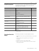
3-6 Segregating Sources and Victims Wire and Cable Categories The table below indicates the best zone for running cables and wires. The table also shows how the use of ferrite sleeves and shielded cable can reduce the noise effects of dirty and very-dirty wires and cables. Note: Some items have two entries (one shielded and one not shielded).
Segregating Sources and Victims Zone Cable and Wire Category 3-7 Method Clean Ferrite Sleeve1 Shielded Cable2 Data/Communications4 X X Encoder/Resolver X X Logic circuit power X X High Speed Registration inputs5 X X PLC Analog I/O X X PLC High Speed Counter input X X VeryDirty Dirty Proximity Switches (except registration) X Photoelectric Cell X 24V dc Relay X Transformer Indicator Lamp X X 1 An X in this column indicates a ferrite sleeve fitted to the wire is recommended.
3-8 Segregating Sources and Victims Minimizing Loops Wires that form a loop make an efficient antennae. Run feed and return wires together rather than allowing a loop to form. Twisting the pair together further reduces the antennae effects. Refer to the figure below for an illustration. Note: This applies to potential victim wiring too. Antennae work equally well in both receive and transmit modes. Figure 3.
Chapter 4 Shielding Wires, Cables, and Components Chapter Objectives Understanding the Shielding Concept This chapter describes how using shielded cable or steel shields can reduce electrical noise coupling.
4-2 Shielding Wires, Cables, and Components In the shielding example below the grey plastic wireway (front) is shielded by 0.7 mm (0.03 in.) thick perforated and plated sheet steel. The perforated steel is easy to cut and bend. You can safely route very-dirty wires in the other (black) wireway behind the shield. Note: By using grey colored wireway for clean zones and black for dirty and very-dirty zones you will see more clearly when shielding is necessary. Figure 4.
Shielding Wires, Cables, and Components 4-3 Figure 4.3 Ferrite sleeves increase common mode impedance Ferrite sleeve greatly increases impedance at RF Signal Source Optional capacitor V Panel A Panel B Differential noise voltage Figure 4.4 Common mode rejection in shielded cable In this physical circuit, the core and shield are effectively connected together at the transmit end. Ferrite Sleeve Transmit Core Receive Core Vn is the noise voltage.
4-4 Shielding Wires, Cables, and Components Ferrite Sleeve Limitations After implementing all the guidelines presented in this manual, a properly built system should perform well without ferrite sleeves. However, by including sleeves in your installation, the system will avoid problems caused during future modifications. System installations can benefit from ferrite sleeves, but you should also realize that ferrite sleeves alone are not a substitute for proper noise coupling reduction techniques.
Shielding Wires, Cables, and Components 4-5 In Figure 4.5 the cable is locally shielded to cross another zone. Each shield is grounded at each boundary and the cable is run close to the panel. The outer shield A is a thick walled steel conduit. Figure 4.5 Very-dirty cable in clean zone Dirty Zone EMC filter to drive 24V dc I/O cable Very-Dirty Zone Dirty Zone Motor power cable Clean Zone Dirty Zone Very-Dirty Zone A Minimum 150 mm (6.0 in.) segregation The principle works both ways. In Figure 4.
4-6 Shielding Wires, Cables, and Components Publication GMC-RM001A-EN-P — July 2001
Chapter 5 Filtering Noise Chapter Objectives Understanding the Filtering Concept This chapter describes how low-pass filters and ferrite sleeves can reduce electrical noise coupling. This chapter covers the following topics: • Understanding the filtering concept • Filter performance • Ultrasonic transducers • AC line filters If sources and victims are connected by wiring, you can prevent noise coupling by filtering.
5-2 Filtering Noise General Purpose 0-24V ac/dc Filters The filter diagram shown below forms a classic LC low-pass filter. Figure 5.1 Filter applied to 24V dc power circuit Floating Common Grounded Common Segregation +24V Com/Neutral IMPORTANT The effectiveness of the LC low-pass filter depends on a perfect bond between the DIN rail and the ground plane panel. Figure 5.
Filtering Noise 5-3 Figure 5.3 Floating-Common filter DIN rail Clean side Capacitors Ferrite Sleeve (choke) Dirty side Forming capacitor leads The table below lists the part description and part numbers for the filters shown in Figure 5.2 and Figure 5.3.
5-4 Filtering Noise Performance Test Set-up The filter performance test included the following components: • 24V dc power supply with grounded common filter • Filter mounted to DIN rail • Relay coil to simulate an inductive load • 100M Hz sampling digital storage oscilloscope • Test components mounted on a large zinc plated steel panel Figure 5.4 Filter test block diagram Measurement point 1 m (39 in.
Filtering Noise Ultrasonic Transducers 5-5 Ultrasonic transducers often induce high noise levels onto their DC supply and signal lines. To reduce noise using ultrasonic transducers: 1. Mount two DC filters close to the device with ferrite sleeves between the capacitors and the sensor. 2. Feed the DC power supply through one sleeve. 3. Bring out the analog signal via the other sleeve. Note: Use shielded cable for the analog signal.
5-6 Filtering Noise Figure 5.5 Line filter earth leakage path L Load Line N Leakage current E Three phase filters are theoretically balanced so the net ground current should be zero. However, a failure of any one capacitor or severe unbalance would cause ground current to flow and trip a circuit breaker. Earth Leakage/Ground Fault Earth Leakage Circuit Breakers (ELCB) and Ground Fault Interrupters (GFI) are typical European and US terms for the same device.
Chapter 6 Contact Suppression Chapter Objectives Understanding Contact Suppression for AC Circuits This chapter describes how contact suppressors for solenoids, relays, and various other switches can reduce electrical noise. This chapter covers the following topics: • Understanding contact suppression for AC circuits • Understanding contact suppression for 24V dc circuits • Contact suppression effects The one potential noise source that the you can reduce directly is a contact switched load.
6-2 Contact Suppression Note: Sometimes the supply to a group of zero-crossing Triac outputs is switched by a mechanical contact for safety purposes. Suppress at the contact in this case. Methods of AC Contact Suppression The typical RC suppressor circuit (shown below) consists of a 0.1 µF capacitor in series with a 100 ohm resistor. These components are readily available from many suppliers. Figure 6.1 RC suppressor circuit 0.
Contact Suppression 6-3 The suppressor across the contact (as shown below, lower) reduces the noise from the wiring inductance as well as the coil inductance. Figure 6.
6-4 Contact Suppression Figure 6.5 Transient absorber +24V dc Good Solution Transient absorber Common +24V dc Better Solution Common Contact Suppression Effects Transient absorber The waveform below displays 7.2V peaks across the AC terminals of a +24V dc power supply. Noise is due to load on the DC circuit being switched. Figure 6.6 Unsuppressed inductive load on the DC circuit 10V 7.
Contact Suppression 6-5 The waveform below displays the effects of an RC suppressor added across the coil on the noise shown in Figure 6.6. Peaks are reduced to 6.4V with significant reduction in duration. Refer to Figure 6.3 (upper) for example of RC suppressor across a coil. Figure 6.7 Effects of RC suppressor mounted at the load 10V 8 6.
6-6 Contact Suppression The waveform below displays the effects of a flywheel diode across the switch (refer to Figure 6.4, lower). The peak voltage is reduced to 0.3V. Figure 6.
Chapter 7 Power Distribution Chapter Objectives This chapter describes bonding, segregating, shielding, and filtering techniques when routing AC and DC power. This chapter covers the following topics: • Understanding noise in power wiring • Three-phase power supplies • Single-phase power supplies • 24V dc power supplies Understanding Noise in Power Wiring AC and DC power wiring usually extends to all parts of a system.
7-2 Power Distribution IMPORTANT The effectiveness of the line filter depends solely on the HF bond between filter case and drive chassis. Commercial filters are tested, as shown in the figure below, with all devices properly bonded to a conductive metal ground plane. Proper bonding techniques are essential to achieve the published attenuation figures. Refer to the chapter High Frequency (HF) Bonding for more information on bonding. Figure 7.
Power Distribution 7-3 Transformers An isolation transformer is frequently assumed to give good noise isolation. In fact, this only applies if the transformer is equipped with one or more electrostatic (ES) shields, as shown in the figure below. Figure 7.3 Electrostatically shielded transformer Primary Secondary Frame bonded to ground plane Ground Plane Shield(s) bonded to ground plane This technique is very effective, though generally EMC filters are required to meet European regulation standards.
7-4 Power Distribution Single Phase Power Supplies 24V dc Power Supplies To avoid noise related problems caused by single-phase power supplies, observe the following guidelines: • Treat single-phase wiring as dirty. • Include line filters for loads that create noise, such as PWM devices with DC switch-mode power supplies and fluorescent cabinet lights. • Include line filters for potentially sensitive loads, such as PLC logic power. • Mount the line filter as close to the load as possible.
Power Distribution 7-5 24V dc Distribution Route power wiring according to clean/dirty zones. Segregate the following load classifications: • Clean loads that are potentially sensitive to noise and which do not create significant noise, e.g. controller logic supplies. • Dirty loads that are insensitive to noise but may emit moderate levels of noise, e.g. relay circuits. Note: Refer to the chapter Segregating Sources and Victims for a detailed listing of categories.
7-6 Power Distribution Single 24V dc Switch-Mode PSU Zoning Example In the figure below, a 24V dc supply is mounted in the dirty zone, because it may create noise. But, the noise is reduced by filtering before the output enters the clean zone. Figure 7.
Power Distribution 7-7 In the figure below, a filter is pictured between the clean zone (grey wireway) and the dirty zone (black wireway). Refer to the chapter Filtering Noise for details regarding filters. Figure 7.
7-8 Power Distribution Dual Switch-Mode 24V dc PSU Example In the figure below, dirty and clean zone loads have dedicated power supplies. Segregation and filtering are used (as in Figure 7.5) to reduce the noise in the power supply for clean zone needs. Figure 7.
Power Distribution 7-9 Linear PSU The linear PSU does not generate noise on its AC terminals, as does a switch-mode supply, however, some noise reduction provisions are still recommended. Linear PSU Mounted in Clean Zone In the figure below, the linear power supply is mounted in the clean zone, but the AC line feeding it requires filtering. The AC line filter is positioned between zones and attenuates line noise which may otherwise be passed through to the DC circuit. Figure 7.
7-10 Power Distribution Linear PSU Mounted in Dirty Zone In the figure below no AC line filter is required because the linear PSU does not generate noise and the AC line noise is filtered by the DC filter. Figure 7.
Power Distribution 7-11 Special Applications for 24V dc PSUs This section contains information considered application specific and does not apply to all installations. Floating Requirement If it is necessary to maintain a floating common, a modified filter may be used to ground the common at HF frequencies only. Refer to the chapter Filtering Noise for details regarding filters. Figure 7.
7-12 Power Distribution Segregation and Filtering Variations Once the principles of segregation and filtering are understood it is possible to vary the strategy to suit special requirements. For example, the clean zone does not have to be a single entity. As shown in the figure below, you can create separate local clean zones. Refer to the chapter Segregating Sources and Victims for guidelines on crossing zones. Figure 7.
Power Distribution 7-13 Long Power Cable Runs The 24V dc lines entering or leaving panels that cannot be bonded together by flat strips (no longer than 10 times the width) should have filters at the point of entry. Figure 7.12 Long cable runs between panels Panel A Panel B +24V 24V com Note: If heavy circulating currents at power frequency are likely, the floating filter technique or separate, local PSU’s, may be safer to use.
7-14 Power Distribution Publication GMC-RM001A-EN-P — July 2001
Chapter 8 Motor Wiring Chapter Objectives Understanding Noise in Motor Power Wiring This chapter describes shielding, grounding, and splicing techniques for use with motor wiring.
8-2 Motor Wiring Shielding Motor Power Cables The benefits of using shielded cable are listed below (also refer to Figure 8.2). • The shield strongly attenuates the electric field (E field) noise. • Core to shield capacitance is added to the stray capacitance at A & C increasing ground currents in the loop A, C, D, E, and F. • These currents generate a magnetic field (H field). It is important to minimize the area of this loop as far as possible by routing the cable close to grounded metalwork.
Motor Wiring Applying Ferrite Sleeves 8-3 A ferrite sleeve around the three power conductors as they leave the drive will help to reduce common-mode noise current. Take all three conductors two or three times through the core. If it runs hot reduce the number of turns. Note: Not all drives allow the use of a ferrite sleeve around power conductors. Refer to your manual for specific applications. Splicing Motor Power Cables Avoid splicing motor power cables when ever possible.
8-4 Motor Wiring Handling Excess Cable Observe the following guidelines when handling excess cable: • Do not coil excess cable of different types (i.e. motor power and feedback) together. An efficient transformer is formed at HF. • Cable lengths should ideally be trimmed to fit the application. • If excess cable cannot be trimmed, it should be laid in an 'S' or figure eight pattern (refer to the figure below). Figure 8.
Chapter 9 High Speed Registration Inputs Chapter Objectives Understanding Registration Inputs This chapter describes how wiring, sensitive to electrical noise, benefits from proper noise reduction strategies. This chapter covers the following topics: • Understanding registration inputs • Noise reduction methods • Power supply wiring options • Signal noise filter options • Registration error High speed registration inputs are potentially sensitive to noise by design.
9-2 High Speed Registration Inputs Noise Reduction Methods This section provides installation guidelines for reducing noise coupling into high speed registration inputs. Wiring Follow these guidelines to reduce noise coupling in wiring: • Always use shielded cable. • Connect shields at both ends and at the circular section. • Always run the cable in a clean zone. • Segregate the cable as far as practical from dirty and (especially) very-dirty wiring.
High Speed Registration Inputs 9-3 Figure 9.1 Shared registration power supply +24V +24V com Dirty Zone Segregation Clean Zone Clean Load Insulated mounting (preferred) + Detector Registration Input com In figure below a pigtail shield connection is used for the short cable run to the input and a clamp connection for the long run from the sensor. Refer to Appendix A for more information on grounding cable shields. Figure 9.
9-4 High Speed Registration Inputs Dedicated Power Supply In the figure below, the registration input has a dedicated linear power supply. Figure 9.
High Speed Registration Inputs 9-5 Proximity Switches Proximity switches are especially vulnerable in the off state since the signal line is disconnected at the switch, forming an efficient antenna. Observe the following guidelines when using proximity switches: Signal Noise Filter Options • Insulate the mounting, if possible, and connect the body to the cable shield. • Arrange to be normally on (i.e. hole-operated instead of target-operated). • Register on the falling edge.
9-6 High Speed Registration Inputs Single Voltage Input (24V or 5V) The figure below illustrates a typical registration filter circuit. Figure 9.4 Registration filter circuit R2 R1 Publication GMC-RM001A-EN-P — July 2001 C • R1 lowers the circuit impedance which improves noise immunity. It also ensures that the signal voltage falls rapidly when the detector turns off. A lower R value is better, but is limited by the drive capability of the detector and the dissipation in the resistor.
High Speed Registration Inputs 9-7 Dual Voltage Inputs (24V or 5V) Where the input is split into 5V and 24V, with inputs sharing the same common, it is important that the 5V input is not left floating. In the figure below, the 24V and 5V inputs are shorted together and fed at 5V. Figure 9.5 Registration filter circuit (24V/5V) +24V +24V +5V R2 From Detector R1 To Registration Inputs C Common Common The on-delay and off-delay times are shown in the table below.
9-8 High Speed Registration Inputs Registration Error The following charts help to estimate the error due to time delays. The detector delay may be much greater than the filter delay, so it is important to add the two together. Figure 9.6 Registration Error vs. Delay (metric units) 10 1 Error mm 0.1 0.01 0.001 0.0001 10 20 50 100 200 500 1000 Linear Velocity m/min 1 uS 2 uS 5 uS 20 uS 50 uS 100 uS 10 uS Figure 9.7 Registration Error vs. Delay (British units) 1 0.1 Error ins 0.
High Speed Registration Inputs 9-9 Figure 9.8 Registration Error vs. Delay (rotary units) 10 Error deg 1 0.1 0.01 0.001 0.0001 20 50 100 200 500 1000 2000 Velocity RPM 1 uS 2 uS 5 uS 20 uS 50 uS 100 uS 10 uS Error Compensation If the registration signal delay is constant, it will have the effect of applying a position error proportional to velocity. In this case it may be possible to apply a software correction.
9-10 High Speed Registration Inputs Publication GMC-RM001A-EN-P — July 2001
Chapter 10 Encoders Chapter Objectives Understanding Encoders This chapter describes bonding, segregating, shielding, and filtering techniques for use with encoders. This chapter covers the following topics: • Understanding encoders • Noise reduction methods • Power supply wiring options Encoder input circuits are, by their nature, potentially sensitive to noise. The signal is typically a square wave of about 500kHz at maximum speed.
10-2 Encoders Wiring • Always use shielded cable (manufacturers usually specify appropriate cable). • Segregate the cable as far as practical from dirty and especially very-dirty wiring. Power • Always use the internal power supply when available. • Ensure the power supply has a clean rating (refer to Figure 10.1 and Figure 10.2 for linear and switch-mode power supply examples). • Use a filter if a switch-mode supply is used (refer to the chapter Filtering Noise for more information).
Encoders Power Supply Wiring Options 10-3 This section provides filtering options of power supply configurations for your encoder. For more information regarding filters, refer to the chapter Filtering Noise. Figure 10.1 Linear power supply example AC Dirty Zone Filter Segregation Clean Zone 5/12V dc Linear PSU Keep short or shield (ground shield on both ends) Insulated mounting and coupling preferred Encoder + Encoder Input com Figure 10.
10-4 Encoders Publication GMC-RM001A-EN-P — July 2001
Chapter 11 Measuring Noise Reduction Effectiveness Chapter Objectives This chapter describes the equipment, methods, and various guidelines for measuring noise reduction effectiveness.
11-2 Measuring Noise Reduction Effectiveness Professional probes are available in each category and would be mandatory for testing to EMC regulations but simple methods are sufficient for this purpose and are described below (refer to Appendix B for EMC suppliers). Measuring Noise This section describes the tools and methods used to measure noise.
Measuring Noise Reduction Effectiveness 11-3 E-Field Sniffing Method The E-field is the electric field capacitively coupled to the probe. To use the E-field sniffing method: 1. Attach a 150 mm (6 in.) length of stiff insulated wire to the probe tip to form an antenna. 2. Remove the probe ground clip or attach it to the scope cable to ensure it does not contact anything. 3. Hold the wire parallel to and touching potential victim wiring and measure the voltage spikes.
11-4 Measuring Noise Reduction Effectiveness H-Field Sniffing Method The H-field is the magnetic field inductively coupled to the probe. Connect the scope probe ground clip to the probe tip forming a small loop. Hold the loop close to potential victim wiring. The loop antenna is sensitive to orientation, so test all three axes to determine the maximum reading at each location. Figure 11.
Measuring Noise Reduction Effectiveness 11-5 Measuring AC Circuits Line voltage AC circuits are more difficult to measure since 50/60Hz AC waveforms will swamp the noise signals if a standard 10x or 100x scope probe is used. Professional noise probes include a 150kHz high-pass filter to attenuate power frequency signals, but such a filter is easily built (refer to Figure 11.3). Figure 11.
11-6 Measuring Noise Reduction Effectiveness For BNC cases (as shown in Figure 11.4) refer to the following list of suppliers: • Pomona Electronics, Part # 3752 • RS Components, Part # 189-0258 For more information on these and other suppliers, refer to Appendix B. Figure 11.4 High-pass filter construction, 150 kHz, 1 pole (signal flow is left to right) ATTENTION ! To avoid personal injury or damage to equipment, always connect the probe ground clip to reference ground.
Measuring Noise Reduction Effectiveness 11-7 Ground Loops A line-powered oscilloscope may introduce noise via the ground loop formed by the separate line supply and the connection of the probe to system ground. Methods to reduce this type of noise are listed below. • Connect a braided strap between the scope chassis and the panel. Most scopes have a ground terminal provided for this purpose. • Pass the scope lead through a ferrite sleeve several times.
11-8 Measuring Noise Reduction Effectiveness • Use a high-pass filter between the probe and the scope input when checking AC circuits. Refer to Figure 11.4 for filter construction details. Note: Before installing the high-pass filter, check that the signal does not overload the voltage probe at the chosen division ratio. Figure 11.5 Typical differential voltage probe Differential Scope Inputs Refer to these guidelines using an oscilloscope with two inputs in differential mode.
Measuring Noise Reduction Effectiveness 11-9 Scope Probe Lead Extension Refer to these guidelines, and the figure below, when extending the scope probe. • Keep the extension cable as short as possible. • Make several turns through the ferrite sleeve. • Only use 1x probes (10x probes will attenuate HF signals by more than ten times). Figure 11.
11-10 Measuring Noise Reduction Effectiveness Identifying the Noise Source Two methods for identifying the source of a noise spike are listed below. • Disable each potential source in turn until the spike disappears. • Correlate the noise signal with PWM sources by displaying the PWM waveform on a second channel. If the PWM source is the culprit, the noise signal will remain synchronized to the edges of the PWM waveform.
Measuring Noise Reduction Effectiveness 11-11 Field Strength Meters Field strength meters (RF sniffers) are commercially available to aid in the alignment of transmitters and antennae. They are small hand-held instruments with a row of LED’s or a meter to indicate level and respond to a wide range of signal frequencies. They appear to be an ideal instrument for measuring noise, but are not.
11-12 Measuring Noise Reduction Effectiveness Monitoring Panels To monitor your system panel: 1. Route a wire around all the clean zone wireways, ensuring that it lays on top of all other wires (furthest from the panel). 2. Measure voltage peaks between one end of the wire and the adjacent panel to assess E-field noise. 3. Repeat with the other end grounded to assess B-field noise. 4. Enable each potential noise source in turn to assess its contribution if required.
Appendix A Noise Control Supplement Chapter Objectives Grounding Cable Shields This appendix is designed to offer additional information on specific topics related to electrical noise control. The topics include: • Grounding cable shields • Wire segregation test results • Switch-mode DC power supplies • Using a dynamic braking contactor • Bonding surfaces This section describes different methods for grounding cable shields. Pigtails To form a pigtail and attach a flying ground lead: 1.
A-2 Noise Control Supplement Clamping at the Circular Section When using a pigtail is not acceptable, clamp your cable to the main panel closest to the shield terminal using the circular section clamping method. Clamping at the circular section or 360° bonding, as shown in Figure A.1 below, is the preferred method for grounding cable shields. Several types of clamps are shown on the next page. Refer to the table associated with each type of clamp for advantages and disadvantages.
Noise Control Supplement A-3 Figure A.2 Cable clamping methods A B C Strapping your cable to a DIN rail, as shown in Figure A.2 (the cable labeled B) is crude, but just as effective. The DIN rail is raised off the panel slightly by using washers to allow nylon cable ties to pass underneath. The table below lists advantages and disadvantages of strapping the cable to the DIN rail.
A-4 Noise Control Supplement Figure A.3 Gland clamping method Conductive gland grounding, as shown in Figure A.3, is only required for extreme applications, such as radar, aerospace, etc. The table below lists advantages and disadvantages of the gland clamp method.
Noise Control Supplement Wire Segregation Test Results A-5 Tests were conducted to obtain objective comparisons between levels of segregation. This section describes how the tests were conducted, the results achieved, and the conclusions reached. Test Set-up The tests were conducted using a typical source circuit, victim circuit, and segregation methods as described below. Source Circuit The loads were switched on and off by mechanical switch contacts.
A-6 Noise Control Supplement Method • Both 24V dc commons were grounded to the panel (refer to Figure A.4). • 500mm parallel wire runs were set up at varying distances apart (separation) and different heights above the panel (wire to panel). • Peak voltages were measured on the victim wire referenced to the panel. Figure A.
Noise Control Supplement A-7 Figure A.5 Wire segregation test results Victim Noise Vpk Wire Segregation Test 500 mm run, unsuppressed relay coil 100 10 40 mm 1 3 mm 0.1 0.01 0 25 50 100 200 Horizontal Separation mm Figure A.6 Wire segregation test panel Conclusions The following statements summarize the results of the testing. • 150 mm (6 in.) is a reasonable minimum separation required even for short runs. • A well grounded steel dividing wall is as good or better than 200 mm (8 in.
A-8 Noise Control Supplement Switch-Mode DC Power Supplies This section describes the advantages and disadvantages of switch-mode DC power supplies and how to reduce common-mode noise. IMPORTANT Switch-mode power supplies do not always isolate noise and may generate common-mode noise on both AC and DC lines. Background Information Switch-mode power supplies have become very popular due to their small size and low weight compared to the traditional 50/60 Hz transformer/rectifier/capacitor construction.
Noise Control Supplement A-9 Grounding the Common Grounding the DC common of the power supply attenuates common-mode noise dramatically. A sample wiring diagram is shown in the figure below. Figure A.
A-10 Noise Control Supplement In Figure A.8, 6.0V common-mode noise spikes are seen at the +24V dc terminal relative to ground. Figure A.8 20A, 24V dc PSU (ungrounded, no-load) 10V 8 6 4 2 0 -2 -4 6.0V pk -6 -8 -10V -1 0 1 2 3 4 5 6 7 9 ms 8 Sitop Power 20 with 3 phase input - no load Common Mode Noise +24 Volts to Backplane In Figure A.9 the noise amplitude is reduced to around 500mV pk, adequate for general-purpose, dirty loads. Figure A.
Noise Control Supplement A-11 DC Filtering If sensitive clean loads are to be connected, further noise reduction is required. A simple low-cost filter is all that is required (refer to the chapter Filtering Noise for an example). A commercial AC line filter can be used, but may not be effective when using long motor cables. The low ringing frequency of such cables may be below the filter break frequency. In Figure A.10 the noise is reduced to around 70mV (clean enough for most industrial applications).
A-12 Noise Control Supplement AC Line Filters Always install a suitably rated AC line filter on the main panel as close as possible to a switch-mode PSU. Using Separate DC Power Supplies It is often assumed that the use of separate DC PSU's will isolate noise. In fact, noise will travel in either direction through a power supply.
Noise Control Supplement A-13 In Figure A.12 noise spikes greater than 2V, from an unsuppressed inductive load are seen on the DC circuit of the second PSU. Figure A.12 Noise spikes on +24V dc terminal of second PSU 10V 8 6 4 2.3V pk 2 0 -2 -4 -6 -8 -10V -1 Using a Dynamic Braking Contactor 0 1 2 3 4 5 Victim Omron +24Vdc DC floating 6 7 8 9 µs Dynamic braking (as shown in Figure A.13) requires the insertion of a three-phase contactor between drive and motor and satisfies two requirements.
A-14 Noise Control Supplement Figure A.13 Typical dynamic brake contactor interconnections Contactors Resistor Resistor Resistor Drive 1 1 1 1 1 1 U U V V W W Motor 2 Unbraided shield Grounded terminal or stud 3 Isolated terminal Enclosure wall Note: Exposed power wiring conductors that are not shielded are a source of RFI noise. Keep exposed conductors as short as possible and isolated from sensitive devices and wiring.
Noise Control Supplement Bonding Surfaces • Segregate unshielded wires at least 150 mm (6.0 in.). • Keep unshielded wiring as short as possible. • Suppress the contactor coil. • Mount all components in a shielded enclosure. A-15 When two or more surfaces (such as panels) require bonding, wide flat braid is preferred to wire due to its low impedance when compared with wire. Wire Forms an Antenna An efficient whip antenna for the 2 m (144 MHz) amateur radio band is just 500 mm (20 in.) long.
A-16 Noise Control Supplement Noise Checklist Use the following checklist to ensure that the number of potential noise sources in your system is reduced and that the noise sensitive components are not affected by the remaining noise.
Appendix B EMC Product Suppliers This appendix contains a list of the EMC product suppliers referenced in this document. The list is not intended to be all inclusive, but the supplier names, products they provide, and websites are given below. Supplier: Product(s): Website/Email: Alpha Wire, Manufacturer (USA) Standard and specialty wire and cable products (e.g. flat and oval braid) www.alphawire.com Chomerics, Div. Parker Hannifin Corp.
B-2 EMC Product Suppliers Publication GMC-RM001A-EN-P — July 2001
Index A A quad B 10-1 AC circuits 11-5 AC line filter 5-1, 5-5, 7-1, 7-4, A-12 acceptable levels 11-10 adjacent panels 2-8 adjacent wires 1-5 analog device 1-4, 3-3, A-11 analog I/O 3-7 anodized components 2-7 antennae 3-8, 9-5, 11-3 B battery power 11-2, 11-7 best practice 1-2 BNC case sources 11-6 bonding See HF bonding build time 3-2 buildings existing 2-13 new 2-12 bulkhead connectors 8-3 C cabinet lights 6-1 cabinet, plated 2-7 cable clamp A-2 cables bulkhead connector 8-3 communication 3-7 data 3-7
I-2 Index switch-mode 3-3 ultrasonic transducer 3-3 component mounting panel 2-6 components anodized 2-7 painted 2-7 contact suppression 6-1 cabinet lights 6-1 contactor 6-1 fluorescent 6-1 relay 6-1 solenoid 6-1 transformer 6-1 contactor 3-3, A-5, A-13, A-15 contents of manual P-2 conventions used in this manual P-3 copper layer 2-4 corrosion 2-7 counter input 3-7 coupling 1-6 capacitive 1-5, 9-1 encoder noise 10-1 inductive 1-5 insulated shaft 10-2 mechanism 1-1, 1-2, 1-4 crossing at right angles 4-4
Index floor grid 2-9 mezzanine 2-10 raised 2-9 fluorescent 6-1 flywheel diode 6-3 frequency range 1-2 G GFI 5-6 gland clamp A-4 grid floor 2-9 ground 7-6 cable shields A-1 component mounting panel 2-6 DC common A-9 DIN rail 2-6, 5-4 drive chassis 2-5 ELCB 5-6 extending the ground plane 2-5 fault 5-6 GFI 5-6 ground plane principle 2-3 grounding your probe 11-6 measuring noise 11-4 PE ground 2-14, 5-5 perforated ground plane 2-13 pigtails 3-7 power cable shields 8-2 safety A-14 safety earth 2-14 single po
I-4 Index motor contactor 3-6, 11-10 motor frame noise 2-2 motor power wiring 8-1 ferrite sleeves 8-3 stray capacitance 8-1 motor starters 3-2 multiple common/ground connections 7-6 mutual inductance 1-5 N noise acceptable noise levels 11-10 checklist A-16 clamping advantages A-2, A-3, A-4 cable A-2 circular section A-2 disadvantages A-2, A-3, A-4 gland method A-4 saddle clamp A-3 component categories 3-3 conducted 1-4 contactor 6-1 E-field 8-2 encoder 2-2 encoder PSU 10-3 grounding cable shields A-1 H-
Index P painted components 2-7 painted panel 2-6, 11-6 panel 2-6, 2-7, 11-12 adjacent 2-8 painted 11-6 plated 11-6 zinc 2-6 panels 2-6 PCB designers 2-4 peak voltage levels 11-10 photoelectric 3-7, 9-4 pigtail 3-7, 8-2, 9-3, A-1 Piltz 3-3 plated panels 2-6, 11-6 PLC 3-2, 3-3, 3-6, 6-1 pneumatic 3-6 position error 9-9 power cable shield 8-2 power distribution 7-1 power supplies 1-2, 7-4 24V distribution 7-5 dual 24 volt power supplies 7-5 floating common 7-11 linear 7-4 segregation and filtering 7-12 separ
I-6 Index strobe lights 5-5 suppression 6-1 effects 6-4 flywheel diode 6-3 RC 6-2 transient absorber 6-2 switching noise 1-3, 2-1, 6-1 switch-mode 1-2, 3-3, 7-4, 10-3, user information 1-2 V victim 1-1, 1-2, 1-4, 1-6, 2-2, 3-1, 4-1, 5-1, A-5 victims of noise See victim A-8 system builder 1-3 system HF bonding 11-11 system tolerance 1-2 T target-operated 9-5 transformer 6-1 transient absorber 6-2, 6-4 transistors 2-2, 2-3 Triac 6-1 true ground 2-3 TTL 11-10 TTL circuits 2-4 TTL victim 1-4 U ultrasoni
Publication GMC-RM001A-EN-P — July 2001 Copyright © 2001 Rockwell Automation, Inc. All rights reserved. Printed in the U.S.A.