8000 SERIES TMR SYSTEM SAFETY MANUAL T8094 ISSUE 27 – JUNE 2013
SAFETY MANUAL Copyright © Rockwell Automation 1998-2013 Printed in England D o c N u m b e r T8 0 9 4 Issue 27 – June 2013 Page ii
SAFETY MANUAL This page intentionally blank D o c N u m b e r T8 0 9 4 Issue 27 – June 2013 Pa g e i i i
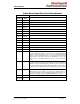
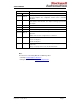
SAFETY MANUAL Issue Record and Record of Amendments Issue Number Changes Date Issue 1 Sep 99 Initial Issue Issue 2 Sep 01 Updated to reflect re-certification as of September, 2001 Issue 3 Nov 01 Updated to reflect 3.0 certification. Issue 4 Mar-02 Updated to add new logo Issue 5 Mar-02 Updated to correct table and figure numbering. Issue 6 May-02 Updated to reflect 3.1 certification. Issue 7 Jan-03 Updated to reflect 3.2 certification.
SAFETY MANUAL Issue Changes Number Date Issue 20 Feb 09 Company logo; master\slave replaced by active\standby; Section 3.7.2 corrected Companion Slot configuration; Added section 6 SYSTEM SECURITY Issue 21 Oct 09 Relevant sections revised due to updated standards; NFPA 72:2007, NFPA 85:2007, NFPA 86:2007.; ICS Triplex Technology replaced with ICST Triplex Issue 22 Nov 12 Update for certification of release 3.5.3. Issue 23 Nov 12 Obsolete – withdrawn.
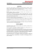
SAFETY MANUAL NOTICE The content of this document is confidential to Rockwell Automation companies and their partners. It may not be given away, lent, resold, hired out or made available to a third party for any purpose without the written consent of Rockwell Automation. This document contains proprietary information that is protected by copyright. All rights are reserved. Microsoft, Windows, Windows 95, Windows NT, Windows 2000, and Windows XP are registered trademarks of Microsoft Corporation.
SAFETY MANUAL PREFACE This Manual contains the recommended Safety Requirements a System Integrator must consider and implement when designing and building a Safety System using the 8000 series range of products. The contents of this Manual have been reviewed by TÜV and all recommendations and comments made by TÜV have been incorporated.
SAFETY MANUAL WARNING RADIO FREQUENCY INTERFERENCE MOST ELECTRONIC EQUIPMENT IS INFLUENCED BY RADIO FREQUENCY INTERFERENCE (RFI). CAUTION SHOULD BE EXERCISED WITH REGARD TO THE USE OF PORTABLE COMMUNICATIONS EQUIPMENT AROUND SUCH EQUIPMENT. SIGNS SHOULD BE POSTED IN THE VICINITY OF THE EQUIPMENT CAUTIONING AGAINST THE USE OF PORTABLE COMMUNICATIONS EQUIPMENT. MAINTENANCE MAINTENANCE MUST BE PERFORMED ONLY BY QUALIFIED PERSONNEL. OTHERWISE PERSONAL INJURY OR DEATH, OR DAMAGE TO THE SYSTEM MAY BE CAUSED.
SAFETY MANUAL ABBREVIATIONS 1-oo-2 1-oo-2D 2-oo-2 2-oo-3 API DIN DIU EMC EMI EUC FB FCR HIFT IL I/O IMB LD MMU MTR PC PST PSU SFC SFOC SIL ST TMR TÜV UPS D o c N u m b e r T8 0 9 4 Issue 27 – June 2013 One-out-of-two One-out-of-two with diagnostics Two-out-of-two Two-out-of-three Application Program Interface Deutsche Industrie-Norm (German Industrial Standard) Diagnostic Interface Utility Electromagnetic Compatibility Electromagnetic Interference Equipment Under Control Function Block Fault Containment
SAFETY MANUAL GLOSSARY Actuators Devices which cause an action (electrical, mechanical, pneumatic, etc.) to occur when required within a plant component. Architecture Organisational structure of a computing system which describes the functional relationship between board level, device level and system level components. ASCII The American Standard Code for Information Interchange. Uses seven bits to represent 128 characters.
SAFETY MANUAL Discrepancy A discrepancy exists if one or more of the elements disagree. DRAM Dynamic Random Access Memory. A type of volatile read/write memory where the data is stored as a short-life capacitive charge. Though high density and low cost are a feature of DRAMs, they require each row address and hence all data to be refreshed frequently. Element A set of input conditioning, application processing and output conditioning.
SAFETY MANUAL Hot Swap IEC 1131 TOOLSET Alternative term for Companion Slot Software used to configure and program the 8000 series TMR system. IEC 61508 IEC61508 is an international covers functional safety, electrical, electronic and electronic systems; hardware aspects.
SAFETY MANUAL MORSE Method for Object Reuse in Safety-critical Environments. Programming and configuration software tool for the Fastflex range of Remote I/O. Output Module Interface that converts output signals from the control system into signals that can actuate external devices. Peer-to-Peer Communications Allows two or more TMR Controllers to communicate with each other. PCM Protocol PCI Mezzanine Card A set of rules governing data flow in a communication system.
SAFETY MANUAL SIL Safety Integrity Level. One of four possible discrete levels for specifying the safety integrity requirements of the safety functions to be allocated to the safety-related systems. SIL4 has the highest level of safety integrity; SIL1 has the lowest. Slot A slot is the term given to the physical allocation of a module within a 483mm (19 inch) frame.
SAFETY MANUAL Communications Interface An intelligent communications module which interfaces between a TMR Controller and an Engineering Workstation, third party equipment or other TMR Controllers. TMR Processor A processor for use in safety-related applications of the 8000 series system. Handles application program execution, diagnostics and reporting functions. The TMR Processor uses three high performance RISC processors based on patented TMR architecture arranged in a lock-step configuration.
SAFETY MANUAL TABLE OF CONTENTS Paragraph Page 1. INTRODUCTION ............................................................................................ 1 1.1 PURPOSE OF SAFETY ............................................................................ 1 1.2 ASSOCIATED DOCUMENTS ................................................................... 2 1.3 TERMINOLOGY ........................................................................................ 2 1.3.1 Safety and Functional Safety .............
SAFETY MANUAL 3.11.5 Communications Interaction .......................................................... 45 3.11.6 Program Testing ............................................................................ 46 3.12 ON-LINE MODIFICATION ....................................................................... 47 3.12.1 Application Program ...................................................................... 47 3.12.2 System Configuration ....................................................................
SAFETY MANUAL 9.6.1 T8162 CS300 Bridge Module ........................................................ 80 9.6.2 CS300 Equipment Power Supplies................................................ 81 9.6.3 PI-616/PI-716 Digital Input Board .................................................. 81 9.6.4 PI-632/PI-732 Analogue Input Board ............................................. 81 9.6.5 PI-626/PI-726 Digital Output Board ............................................... 82 9.6.6 PI-627/727 Digital Output Board ....
SAFETY MANUAL ILLUSTRATIONS Figure 1 - Simple Triplicated System ................................................................... 5 Figure 2 – TMR Architecture ................................................................................ 6 Figure 3 - Single High Density TMR I/O Module Architecture ............................ 23 Figure 4 - SmartSlot or Adjacent Slot TMR Module Configuration .................... 24 Figure 5 – 2-oo-3 voting logic with discrepancy reporting .............................
SAFETY MANUAL D o c N u m b e r T8 0 9 4 Issue 27 – June 2013 P a g e xx
SAFETY MANUAL This page intentionally blank D o c N u m b e r T8 0 9 4 Issue 27 – June 2013 Pa g e xxi
SAFETY MANUAL SAFETY MANUAL 1. INTRODUCTION 1.1 PURPOSE OF SAFETY The 8000 series TMR system has been designed and certified for use in safety related applications. To ensure that systems build upon these foundations, it is necessary to impose requirements on the way such systems are designed, built, tested, installed and commissioned, operated, maintained and de-commissioned.
SAFETY MANUAL 1.2 ASSOCIATED DOCUMENTS The following documents are associated with the safety requirements applicable to the TMR system or provide supporting information via TUV web Site.
SAFETY MANUAL 1.3.1 Safety and Functional Safety Safety: The expectation that a system will not lead to risk to human life or health. Safety is traditionally associated with the characteristics or hazards resulting from the system itself; including fire hazards, electrical safety, etc. The requirements to be satisfied by the integrator here include wiring, protective covers, selection of materials, etc.
SAFETY MANUAL 1.3.3 Process Safety Time (PST) Every process has a safety time that is the period that the process can be controlled by a faulty control-output signal without entering a dangerous condition. This is a function of the process dynamic and the level of safety built into the process plant. The Process Safety Time1 (PST) can range from seconds to hours, depending on the process.
SAFETY MANUAL applications. To detect the presence of these covert faults, it is necessary to perform tests, or diagnostics on the system. Detection of the covert fault is then used to force the system to its fail-safe condition. For a non-fault tolerant (simplex) system with diagnostics, this is referred to as 1-oo-1D. Fault tolerant systems have redundant elements that allow the system to continue operation or to ensure that the system fails safety in the presence of faults.
SAFETY MANUAL A failure in any element of each channel, e.g. Ch. A Input, will result in that complete channel’s failure. If this failure is fail-safe, only 1 of the remaining channels needs to respond to a demand condition to generate the safe reaction. If a second channel fails safe then the overall system will fail-safe. This is therefore a 3-2-0 architecture.
SAFETY MANUAL 1.4 THE 8000 SERIES OVERVIEW The TMR system is based on a triplicated microprocessor with internal redundancy of all critical circuits. The system controls complex and often critical processes in real time - executing programs that accept external sensor signals, solving logic equations, performing calculations for continuous process control and generating external control signals.
SAFETY MANUAL 2. SAFETY PRINCIPLES 2.1 INTRODUCTION This paragraph provides an overview of generic safety principles with emphasis on the system integration process. These principles are applicable to all safety-related systems, including, but not limited to, the 8000 series system. 2.2 SAFETY MANAGEMENT A prerequisite for the achievement of functional safety is the implementation of procedural measures applicable to the safety lifecycle; these are collectively referred to as a Safety Management System.
SAFETY MANUAL 2.2.
SAFETY MANUAL 2.2.1.3 Safety Requirements The functional requirements shall be analysed to determine their safety relevance. Where necessary, additional requirements shall be established to ensure that the plant will fail-safe in the case of failures within the plant, the safety-related system, external equipment and communications or the safety-related system’s environment. For each safety-related function the required safety requirements class and safetyrelated timing requirements shall be defined.
SAFETY MANUAL 2.2.1.5 Application Programming An overall Application Program software architecture is to be defined. architecture will identify the software blocks and their allotted functions. This The application architectural design shall be used to define the additional requirements resulting from the system hardware design. Specifically, methods for addressing system specific testing, diagnostics and fault reporting are to be included.
SAFETY MANUAL 2.2.1.8 Installation and Commissioning The system installation stage shall define the steps to be undertaken to ensure that the system is installed correctly and commissioned on the plant. These steps shall include the physical and electrical installation of the system. The installation environment is a potential source of common cause failure. Therefore, it is vital that compatibility of the equipment is established.
SAFETY MANUAL 2.2.1.9 Safety System Validation Safety system validation shall test the integrated system to ensure compliance with the requirements specification at the intended safety requirements class. The validation activities should include those necessary to establish that the required safety functions have been implemented under normal start-up, shutdown and abnormal fault modes.
SAFETY MANUAL 2.2.1.10.2 Field Device Maintenance During the lifetime of the system, it will be necessary to undertake a number of field maintenance activities that will include re-calibration, testing and replacement of devices. Facilities should be included within the system design to allow these maintenance activities to be undertaken. Similarly, the operating and maintenance plan needs to include these maintenance activities, and their effect on the system operation and design.
SAFETY MANUAL • Methods for detecting systematic failure that may affect other elements of the system or other systems, and links to the satisfactory resolution of the issues. • Procedures for tracking all reported anomalies, their work around and/or resultant corrective action where applicable. 2.2.1.11 System Modification Design changes will inevitably occur during the system lifecycle; to ensure that the system safety is maintained, such changes shall be carefully managed.
SAFETY MANUAL 2.2.1.12 Decommissioning The procedure for decommissioning the system shall be defined. This procedure is to include any specific requirements for the safe decommissioning of the system and, where applicable, the safe disposal or return of materials. As with commissioning, it is likely that the decommissioning be performed in a phased manner. The decommissioning procedure shall ensure that a plan be developed that maintains the functional safety whilst the corresponding hazards are present.
SAFETY MANUAL 2.3.1 Competency The achievement of functional safety requires the implementation of the safety lifecycle and ensuring that persons who are responsible for any safety lifecycle activities are competent to discharge those responsibilities. All persons involved in any safety lifecycle activity, including management activities, shall have the appropriate training, technical knowledge, experience and qualifications relevant to the specific duties they have to perform.
SAFETY MANUAL 3. SYSTEM RECOMMENDATIONS 3.1 INTRODUCTION This paragraph expands on and applies the safety principles described earlier in this Manual. Many of the recommendations within this paragraph are equally applicable to other safety-related systems. However, the details of the recommendations or requirements are specific to the TMR system. 3.2 I/O ARCHITECTURES The TMR system has very comprehensive internal diagnostics that reveal both covert and overt failures.
SAFETY MANUAL 3.2.1 Safety-Related Configurations TÜV Certified Configuration TMR Processor TMR Processor Software board definitions Dxpdi16, Dxpdo16, Dxpai16, Dxpao16, Dxpdi128, Dxpdi128 & dxpnc40 Peer to Peer Software board definitions Dxpai128 & Dxpao128 Certified as safety-related and can be used for safety-critical applications in SIL 3 in single module or active/standby configurations.
SAFETY MANUAL Digital Inputs 8403, Triplicated, 24 VDC TÜV Certified Configuration Conditions Internal 2oo3 (2oo3 implemented in a single module) Normally energized (de-energize to trip): certified SIL 3. Normally de-energized (energize to trip): certified only for applications that fulfil the requirements under section 3.2.4. Internal 1oo2D (1oo2 implemented in a single module) Normally energized (de-energize to trip): certified SIL 3.
SAFETY MANUAL Speed Monitor Module 8442, Triplicated, Pulse Generator 8444, Triplicated, 24VDC Zone Interface 8448 Triplicated, 24VDC TÜV Certified Configuration Conditions Internal 2oo3 (2oo3 implemented in a single module) Inputs: Within the manufactures specified safety accuracy limits. Outputs: Normally energized (de-energize to trip relays). Normally open or Normally closed Contacts can be used Certified SIL 3.
SAFETY MANUAL Conditions Controller Chassis 8100 Expander Chassis 8300 Certified as safety related and can be used for safety critical applications in SIL 3 Certified as safety related and can be used for safety critical applications in SIL 3 820X Certified as safety related and can be used for safety critical applications in SIL 3 together with either of the following power supply units providing reinforced insulation according to EN60950.
SAFETY MANUAL 3.2.2 High-Density I/O The High-Density I/O modules are either inherently triplicated or dual redundant with comprehensive self-test and diagnosis facilities. The self-tests are co-ordinated to ensure that a majority can be established even in case of a demand during the execution of the tests. Discrepancy and deviation monitoring further enhance the verification and fault detection. The TMR Processor tests internal interfaces to the controller.
SAFETY MANUAL Standby Module Ch. A Ch. A Ch. B Ch. B Ch. C Ch. C Active Module Figure 4 - SmartSlot or Adjacent Slot TMR Module Configuration The High Density I/O modules support the system’s inherent TMR architecture. To annunciate the failure, diagnostic and status information is available within the corresponding module information available to the application programmer.
SAFETY MANUAL 3.2.3 Analog Input Safety Accuracy When High Density Analog input modules are used, the system uses the median value. The deviations between the redundant channels’ measurements are monitored to determine if they are within the safety accuracy limit, refer to the associated module’s Product Description for its safety accuracy specification. When a single channel measurement exceeds the safety accuracy limit then a discrepancy alarm is set for the input channel.
SAFETY MANUAL 3.2.5 EN 60204 Category 0 & 1 Configurations The system is fully compliant for use with category 0 application (de-energise to trip). Category 1 configurations require a controlled stop with power available to the machine actuators to achieve the stop and then removal of power. The 8000 system has a defined internal fail-safe state as de-energised. This could result in the defined shutdown delay being shortened in some cases of I/O failure, CPU failure or loss of power to the system. 3.2.
SAFETY MANUAL 3.2.8 NFPA 86 Requirements The 8000 system is certified to be used in NFPA 86 compliant systems. The systems should be integrated in accordance with NFPA 86. In particular the following shall be applied.
SAFETY MANUAL 3.2.9 EN54 Requirements The 8000 system is certified to be used in EN 54 compliant systems. The systems should be integrated in accordance with EN 54. In particular the following shall be applied. • Where an alphanumeric display is used to display indications relating to different functional conditions these may be displayed at the same time. However for each functional condition there shall be only one window, in which all of the fields relating to that functional condition are grouped.
SAFETY MANUAL [EN54 section 7.
SAFETY MANUAL 3.3 SENSOR CONFIGURATIONS It is recommended that safety critical process inputs be measured using redundant input sensors. Some applications may require multiple sensors and I/O points per safety function In safety critical input applications using a single sensor, it is important that the sensor failure modes be predictable and well understood, so that there is little probability of a failed sensor not responding to a critical process condition.
SAFETY MANUAL 3.4 ACTUATOR CONFIGURATIONS As with sensor configurations it is recommended that redundant actuator configurations be used for safety-critical applications. Some applications may require multiple actuators and I/O points per safety function In safety-critical applications using a single actuator, it is important that the actuator failure modes be predictable and well understood, so that there is little probability of a failed actuator not responding to a critical process condition.
SAFETY MANUAL 3.6 PROCESSOR CONFIGURATION 3.6.1 Timing The TMR Processor supports a limited set of configuration options; the system will verify many of the configuration options, for example module locations against actual module types. The configuration options include the maximum application program scan time and sleep period between application program scans. It is important to ensure that the overall application program scan period (scan and sleep periods) be set according to the PSTE. 3.6.1.
SAFETY MANUAL 3.6.2 Diagnostic Access The TMR Processor supports comprehensive diagnostic facilities. Some of these facilities have the capability of modifying the system’s operation and are therefore password protected, to provide access protection in addition to that afforded by physical access to the system. The password is defined in the Security section of the system.ini file. The password is encoded and is not readily decodable from the system.ini text file.
SAFETY MANUAL 3.7.1.1 SYSTEM Section Configuration The High Density I/O SYSTEM section within the system.ini file allows the internal bus activity, system watchdog and power failure signal and bypass timeouts to be adjusted. These may be adjusted for test and development purposes. Internal Bus Activity (IMBTO) The default setting (500ms) for the internal bus activity timeout is appropriate for most applications.
SAFETY MANUAL 3.7.1.6 De Energised Short Circuit Detection Section This section allows the user to enable the de-energised short circuit detection (default is disabled). Safety related I/O that is normally De-Energised shall use short circuit monitoring (see section 3.2.4). 3.7.2 Module Replacement Configuration The system supports 3 forms of High Density I/O module replacement: a. Hot-swap pair (companion slot) b. SmartSlot c.
SAFETY MANUAL 3.8 INPUT AND OUTPUT FORCING Locking and forcing of individual inputs and outputs from the IEC1131 Workbench are supported for engineering, installation and commissioning purposes. In-service, maintenance overrides for safety-related inputs and outputs should be implemented using the application program.
SAFETY MANUAL 3.9 MAINTENANCE OVERRIDES Maintenance Overrides set inputs or outputs to a defined state that can be different from the real state during safety operation. It is used during maintenance, usually to override input or output conditions in order to perform a periodic test, calibration, or repair of a module, sensor or actuator.
SAFETY MANUAL 3.10 PEER COMMUNICATIONS CONFIGURATION Peer Communications allows safety-relevant data to pass between numbers of 8000 series TMR systems. When using this mechanism, as with any other, it is important to ensure that the overall system will respond within the required PSTE. This requirement applies to normal operation and in the presence of faults. For safety-related applications, it is recommended that the Peer-to-Peer Communications use redundant networks.
SAFETY MANUAL support multiple Ethernets, routing to the dedicated TMR system network shall be specifically disabled.
SAFETY MANUAL 3.11.1 IEC1131 Workbench Configuration The IEC1131 workbench supports 16 levels of password access, level 0 being the highest access level. Each workbench function (for example, viewing, editing, compiling, downloading) may be identified for use only by users with an access level above a certain level.
SAFETY MANUAL 3.11.2 Language Selection The IEC1131 TOOLSET offers many programming tools to develop algorithms to meet the needs of virtually any real-time control application. The configuration and programming languages approved for use in SIL 3 safety related application is shown in Table 8.
SAFETY MANUAL 3.11.3 Testing of New or Previously Untested Functions The TMR system Tool set comprises a number of function blocks that can be combined together to form a project application. The use of these function blocks in safety certified systems is only permitted once they have been tested for correct operation. A list of the functions tested prior to the initial certification the TMR system is provided in section 5 of this Manual.
SAFETY MANUAL 3.11.3.5 Test Results Register Each harness shall include registers that record the functionality of the function block. This registration should be as comprehensive as possible and should utilise as many predictable features as possible. For example, a 2 input logical “Or Gate” stimulated by the two lower bits of a 16-bit counter will record 32768 logical high states if the counter is allowed to make one complete up count from 0 to 65536.
SAFETY MANUAL 3.11.4 Application Development The application program development shall follow a structured approach and follow the principles defined in para. 2.2.1.5. The stages defined in the following sub-sections shall additionally be applied for safety related applications. 3.11.4.1 Partitioning the Application It is impractical and unnecessary to apply the same degree of rigorous development and testing to all functions within the Application where some of those functions are not safety related.
SAFETY MANUAL Each safety function shall be responsible for the control of the corresponding outputs. Sharing of outputs between functions shall not be permitted. 3.11.4.4 Individual Safety Related Functions The TMR system IEC1131 TOOLSET allows the definition of up to 250 individual programs within a single project. This facility should be exploited to enable the allocation of individual safety related functions to separate programs.
SAFETY MANUAL 3.11.6 Program Testing Even with a small number of inputs, it is possible to reach a point where the number of tests becomes unreasonable. Eliminating impossible or unlikely scenarios should be used to reduce the number of logic path tests that need to be performed. The selection of what constitutes a scenario that does not require testing can be performed only after a suitable hazard analysis.
SAFETY MANUAL After an application has been tested, and before any changes are made, a reference copy of the compiled application should be made. After the application has been modified, the new application is compared to the original application by using the TicDiff utility. The utility will identify those programs that have changed since the original application and are subject to re-test.
SAFETY MANUAL The existing application program must be archived before any changes to the application are carried out. Where it is necessary to perform on-line modifications, caution shall be taken to ensure that unsafe responses are not generated. Particular consideration shall be given to the effects during the transition between the existing and the new programs and configurations. This is particularly important where a number of interacting systems provide the required safety functions.
SAFETY MANUAL consider the localised heat generation and its impact on the overall system operating environmental conditions. Table 9 defines the climatic conditions for the modules within a system as a whole. It is possible to achieve a system capable of operation in a wider range of climatic conditions using detailed analysis of the characteristics of the system and resultant conditions for the equipment mounted within the system.
SAFETY MANUAL 3.13.2 Electromagnetic Compatibility (EMC) The TMR system is designed and tested to be resistant to usual levels of conducted and radiated electromagnetic interference and electrostatic discharge. The levels of electrical environmental noise depend on the design of the equipment installation, wiring, other installed equipment, and how near it is to the TMR equipment.
SAFETY MANUAL 3.13.3.2 Preparing and Earthing the Controller Chassis Install module blanking panels (shields) on all empty module positions in the TrustedTM T8100 controller chassis. This will reduce the strength of unwanted electromagnetic emissions during system commissioning and maintenance work when the enclosure doors are open. The chassis must be connected to the EMC enclosure using a cable no smaller than 2 4mm area and no longer than 200 mm. 3.13.3.
SAFETY MANUAL the sufficient current be available to ensure their protective action and that the protective device can break the maximum prospective fault current. • Ensure that the power distribution media is sized to accommodate the maximum prospective fault currents and tolerable voltage losses. This is specifically important where floating supplies are employed and other power sources may result in high prospective fault currents in the event of multiple earth-fault conditions.
SAFETY MANUAL 4. CHECKLISTS This section provides a number of example checklists, these are provided as an aid for competent engineers. In general each checklist item should result in “yes”, where this is not the case a justification should be produced. 4.1 PRE-ENGINEERING CHECKLISTS The checklists provided within this section are applicable to the requirements. It should be recognised that the requirements will undergo refinement, particularly, in the early stages of a project.
SAFETY MANUAL 4.1.2 Functional Requirements Checklist Description Reference Is the definition of each of the required functions complete? 2.2.1.2 Are the interfaces, signals, and data associated with each function clearly identified? 2.2.1.2 Where a ‘tag referencing’ scheme is used for these signals, has a summary description of the naming convention been provided to facilitate an understanding of the role of the signal? 2.2.1.
SAFETY MANUAL 4.1.3 Safety Requirements Checklist Description Reference Have all of the functional requirements been allocated a required safety requirements class? 2.2.1.3 Has the safety-related timing for each safety-related function, including process safety time (PST) and fault tolerance period, been established? 2.2.1.3 Have the safety requirements been approved? 2.2.1.
SAFETY MANUAL 4.2 ENGINEERING CHECKLISTS 4.2.1 I/O Architecture Checklist Description Has the PSTE been established? Reference 1.3.3 and 2.2.1.3 What is the PSTE? Has the fault detection time for the system been established? 3.2.
SAFETY MANUAL Description Reference Has the allocation of signals to I/O modules and channels considered each of the signals’ function? Ensure that potential module and power group failures result in either continued safety function or fail-safe operation. 3.2.1 Do safety related inputs and outputs use only those configurations identified as safety related 3.2.
SAFETY MANUAL 4.2.3 Override Requirements Checklist Description Reference Are the effects of overriding fully understood, particularly where the override action will affect independent parts of an application? 3.9 Has a method of enabling, or more importantly removing, the overrides for the system as whole, or individual sub-systems, been provided? 3.
SAFETY MANUAL 4.2.4 High Density Module Configuration Checklist Description Reference For each of the I/O signal types, do the I/O module settings provide the correct characteristics and behaviour for the intended sensor or actuator? 3.7.1 Have the thresholds been verified with both increasing and decreasing field signal levels and with margins to allow for the accuracy and calibration to ensure that they do not result in overlapping bands? 3.7.1 Is consistent use made of front panel indicators? 3.
SAFETY MANUAL 4.2.6 Testing Description Reference Have all of the functions used been fully tested? 3.11.2 and 3.11.3 Has the program been fully tested? The code checker can be used to highlight which programs have changed during modification see para. 3.9.12.2. 3.11.
SAFETY MANUAL 5. PREVIOUSLY ASSESSED FUNCTIONS The following list shows those function blocks that have been proven safe to use in Certified systems.
SAFETY MANUAL Register Control (SHR) Shift Right Data Conversion (Boo) Converts any variable to a Boolean (Ana) Converts any variable to an Integer (Tmr) Converts a variable for use by a timer Triplex Technology Ltd.
SAFETY MANUAL 6. SYSTEM SECURITY Serial networks are closed and local, and have limited protocol functionality. They are therefore immune to any attack except local deliberate sabotage. Trusted systems, however, with their Engineering Workstations and DCS are Ethernet networks which tend to be part of a larger corporate network which opens up limitless possibilities for accidental or malicious infection or attack. There are some simple steps that can be taken to help prevent such issues.
SAFETY MANUAL APPENDIX A 7. LOW-DENSITY I/O The Low-Density I/O modules provide internal TMR interfacing. Other elements of individual modules may be non-redundant (depending on module type) to support ‘slice redundancy’ in redundant module configurations. To optimise the system’s safety availability, the self-test functions are timed to take only a small part of the system resources.
SAFETY MANUAL will then take up the fail-safe (logic ‘0’) condition. This is not fault tolerant and only becomes fail safe after the fault detection period or test interval. If the sum of the TI, and 2× Tscan is not less than PSTE, then an alternative I/O architecture shall be chosen. 2. Guarded output modules provide a one-out-of-two (1-oo-2) structure within a single module.
SAFETY MANUAL Guarded Digital Outputs T7461A, 24 VDC T7485 L/H, 120 VAC Monitored Guarded Outputs T7481, 24 VDC T7484, 110 VAC TÜV Certified Configuration Conditions Fail-safe single module (1oo1) or Fault tolerant dual modules (2oo2) Normally energized (de-energize to trip): certified. Normally de-energized (energize to trip): certified only for applications that fulfil the requirements under section 3.2.
SAFETY MANUAL 7.1.3 TX and DX Low Density module types in Safety applications. When Using DX and TX Low Density I/O Structures certain defensive measures are needed. These structures provide discrepancy and error information but do not take any cognisance of Second Fault occurrence time. If these structures are used in a safety function it is required that the logical state of each channel be defaulted to a safe state within the logic.
SAFETY MANUAL The sample application logic above uses a 5 second discrepancy timeout period. The actual timeout period used should be based on the process safety time, and must not exceed the second fault occurrence time. In safety related systems the logical state from DX type modules must be forced to the safe condition by the application program if the error bit for that channel is set to a “1”.
SAFETY MANUAL APPENDIX B For guidance on how to upgrade a Triguard SC300E system to a hybrid Trusted/SC300E system, see application note AN-T80015. 8. TRIGUARD I/O The Triguard I/O modules provide internal TMR interfacing. Other elements of individual modules may be non-redundant (depending on module type) to support ‘slice redundancy’ in redundant module configurations. To optimise the system’s safety availability, the self-test functions are timed to take only a small part of the system resources.
SAFETY MANUAL TÜV Certified Configuration Simplex Triguard Interface, 8161 Local Chassis Interface, MBB Remote Slave Interface, MRB01XS Remote Master Interface MRB04XM (2003 implemented in a set of three modules) Simplex (2003 implemented in a set of three modules) Simplex (2003 implemented in a set of three modules) Simplex (2003 implemented in a set of three modules) Conditions Certified as safety related and can be used for safety-critical applications in SIL 3.
SAFETY MANUAL Digital Outputs MDO32BNS, TMR, 24 VDC TÜV Certified Configuration Conditions Internal 2oo3 Normally energized (de-energize to trip): certified SIL 3. (2oo3 implemented in a single module) MDO16GNS, TMR, 48VDC Normally de-energized (energize to trip): certified only for applications that fulfil the requirements under section 3.2.4. May be used in single module or active/standby configurations.
SAFETY MANUAL 8.2 SAFETY RELATED INPUTS AND OUTPUTS The Safety Loops, Cause and Effect Charts or other design data will define which loops are to be considered as Safety Loops. All inputs and outputs associated with Safety Loops must follow the design guidelines laid out in this section. All Modules must be configured for 320 fail safe operation. All output modules associated with Safety Loops must be configured with adjacent hot repair partner slots.
SAFETY MANUAL 8.2.1.2 Analogue Inputs Analogue transmitters are used to monitor safety parameters and inherently provide an increased level of diagnostics with respect to a simple fail-safe digital input. Analogue signals always provide values within a set operating range. For safety related transmitters this should be 4-20mA or 1-5 volts allowing for fault indication below say 3mA (0.75V) and 20mA (5V). If over-range detection is required a 0-10V input module must be used.
SAFETY MANUAL 8.2.1.3 Fail Safe Analogue Processing For each Analogue Input variable received by the system, three values are generated, one from each channel. Under normal operation (transparent to the application) a standard mid-value selection algorithm is used selecting the middle value (assuming all three values are within the health window) to be passed on to the application.
SAFETY MANUAL 8.2.2.2 Multiple Input / Output Safety Configuration Where the safety integrity level requires multiple sensors and final elements from a safety loop, then these configurations will be as follows. 8.2.2.3 Dual Sensors These will be voted by the application logic in a 1oo2 manner such that either sensor providing an alarm status requires a shutdown.
SAFETY MANUAL APPENDIX C 9. MIGRATING A CS300 CONTROLLER 9.1 OVERVIEW TM You can migrate the I/O of an existing CS300 controller to a Trusted system. The migration process lets you retain the hardware and wiring of the existing I/O, and take advantage of the benefits of a TrustedTM system. This appendix defines how to safely migrate an existing CS300-based system to a TM Trusted system for a Safety Instrument Function while retaining the DIN19250/AK6 certification of the original system.
SAFETY MANUAL 9.2 GLOSSARY The definitions which follow are related to CS300 hardware and are used in only this appendix of this manual. ICCB PI PIM TM Integrated computer control board (the legacy CS300 processor board) Process Interface Process Interface Module Termination Module 9.3 ASSOCIATED DOCUMENTS 9.3.1 Specifications AN-T80014: Application Note, Trusted Automation. TM / CS300 Migration Process. Rockwell BASS 0257: CS300 Safety System Application Guidelines. Rockwell Automation.
SAFETY MANUAL Item Description Part No.
SAFETY MANUAL TM A complete list of all the Trusted table. Table 19 - Trusted Item 1 2 3 4 5 TM items needed for the migration is written in the Items Needed for the Migration Description T8100 controller chassis T8110B TMR processor T8162 CS300 bridge module (qty 3) TC 324-02 CS300 interface cable connector card TC 322-02 CS300/SC300E interface cable assembly T8311 expander interface module T8312 expander interface adaptor T8151B communication interface 6 7 8 Remarks 9.
SAFETY MANUAL The migrated system will support the pre-existing configuration of the CS300 I/O modules. Communications which existed from the legacy CS300 system to workstations, printers and distributed control systems must be provided through the T8151 communications interface module. PI-664/PI-774 serial communication board(s) (if fitted) must be removed. The system checks output module signals by test routines within the migrated application or by using output line monitoring units.
SAFETY MANUAL Address Jumpers The TrustedTM chassis is designated Chassis 1. The original primary rack of the CS300 controller which was designated Chassis 1 is now logical Chassis 2, Chassis 2 (if present) is now logical Chassis 3, and so on. All communications to workstations and DCS systems are through the TrustedTM communication interfaces. For more details about the CS300 bridge module refer to PD-T8162. 9.6.
SAFETY MANUAL The Trusted processor constantly monitors the analogue data input from the CS300 slices. When a discrepancy greater than 1% is detected between two slices a fault is declared. 9.6.5 PI-626/PI-726 Digital Output Board The PI-626/PI-726 voted digital output board receives inputs from each of the T8162 CS300 bridge modules, votes on the inputs, and produces one voted output per channel.
SAFETY MANUAL 9.7 SITE PLANNING AND INSTALLATION DESIGN 9.7.1 Operational Environment Make sure that the intended operational environment meets the published specifications for the Trusted system, including the T8162 CS300 bridge module. The temperature of the CS300 equipment enclosure must be monitored by at least two temperature sensors and an alarm created if the panel exceeds the designed maximum operating temperature.
SAFETY MANUAL Make sure that you have application backups which are representative of the running system. In particular, the system configuration files and application logic in the backups must be identical to the files in use in the original system at the time of the upgrade. 9.9.2 Choosing Application Logic The TrustedTM system supports Ladder Logic, and so it is possible to use Ladder Logic for the new application. This will minimise the changes and training requirements for existing users. 9.9.
SAFETY MANUAL The library reduces application complexity. • 9.10.2 Hardware Arrangements The autotest of the I/O works at the application level and uses dedicated input and output ports to stimulate and monitor I/O behaviour. The autotest functions work with the arrangements of additional input and output ports shown in figures C2 thru C5. These input and output ports are standard I/O, and appear to the application in exactly the same way as the I/O being tested.
SAFETY MANUAL Term Meaning or origin Type FRQ HR frequency hour (current time) analogue analogue IP process input analogue IPA input A Boolean IPB input B Boolean IPV LF MDA Boolean Boolean Boolean Boolean output from termination assembly B to RMET Boolean Boolean analogue input used to start a test sequence output from LFLT to application input configuration parameter to LFLT OPA input verification line fault monitor discrepancy A monitor discrepancy B manual test start open circuit op
SAFETY MANUAL 5. 6. 7. 8. 9. this, the migrated application must use triggered application cycles with an interval equal to or greater than the required settling time. TM You must disable the Trusted latent fault detection (LFD) feature for outputs connected through the CS300 equipment. This will prevent spurious TrustedTM fault reports. You must do an analysis of the safety instrumented functions to find out how frequently the autotests must run.
SAFETY MANUAL The ITSTM supports one method of operation (simplex or duplex) and one test schedule and so, if all the input channels are simplex or duplex (but not a mixture of the two), and it is applicable to do tests on all of the inputs at the same time, the application can use only one ITSTM to manage all of the tests. In other circumstances, do the following: • • • If it is necessary to do tests on different inputs at different times, you have to use multiple ITSTMs.
SAFETY MANUAL • These limits apply to all analogue input modules and all configurations of termination module. The application must use calibration drift monitoring for analogue inputs: • One of the 16 channels on each analogue input card must be wired to a known calibration source and a diagnostic ladder used to monitor for drift and to provide the alarm. • The calibration reference must be chosen to reflect the highest level for which the input module is intended to read.
SAFETY MANUAL represents the master control relay for each slice and must be set true leaving 15 channels available as field outputs. Output testing must occur only when all 15 channels in the group are commanded on. The LED indication on TM117-RME/SME shows the commanded state and not the physical state. The rules for Structured Text put a limit on the quantity of inputs and outputs on a function block.
SAFETY MANUAL 9.10.4.7 Commissioning a System and Repairing Faults The ITSTM and OTSTM each have a MTS (manual test start) command. The MTS is useful during commissioning, to make sure that a test is fully operational, and after repairing a fault, to make sure that the repair is satisfactory. You can use the AB (abort) command to stop a manual test immediately, to finish the verification.
SAFETY MANUAL 9.10.5 Function Block Specifications 9.10.5.1 ITSTM – input test manager 9.10.5.2 DIPT – digital input point test 9.10.5.
SAFETY MANUAL 9.10.5.4 RMET – RME test 9.10.5.5 LFLT - line fault line test 9.10.5.
SAFETY MANUAL 9.10.6 Parameter Specifications 9.10.6.1 AB, abort Purpose: Data type: Direction: Values: Notes: The AB (abort) control input lets the user application cancel the execution of an on-going sequence of tests. Boolean From user application to ITSTM From user application to OTSTM TRUE FALSE Default: FALSE The AB input is edge triggered. On a rising edge any test in progress is aborted. 9.10.6.
SAFETY MANUAL Direction: Values: From ITSTM to each DIPT not specified 9.10.6.7 DOM, digital output mode Purpose: Data type: Direction: Values: The DOM (digital output mode) is an encoded output from the OTSTM to each RMET. It is not for direct use by the user application. analogue From OTSTM to each RMET not specified 9.10.6.
SAFETY MANUAL 9.10.6.13 IPV, input verification Purpose: Data type: Direction: Values: Notes: The IPV (input verification) output represents the field input of the channel. Boolean From DIPT to application TRUE – input channel (voted) high FALSE – input channel (voted) low IPV is the voted input state to be used by the application. 9.10.6.
SAFETY MANUAL Data type: Direction: Values: the user application. analogue From RMET to UNPACK16 0 to 65,535 (bit-packed integer) 9.10.6.20 PACK16, a packing of 16 bits Purpose: Data type: Direction: Values: PACK16 carries 15 digital output channels and a test channel. It is not for direct use by the user application. analogue PACK16 to RMET 0 to 65,535 (bit-packed integer) 9.10.6.
SAFETY MANUAL 9.10.6.26 STM, start time Purpose: Data type: Direction: Values: Notes: The STM (start time) parameter sets the hour value of the time of day when the ITSTM or OTSTM will start its first test sequence of the day. analogue From application to ITSTM or OTSTM 0 to 23 A value outside the range 0 to 23 is taken to be 12 9.10.6.27 TA, test active Purpose: Data type: Direction: Values: The TA (test active) output lets an ITSTM or OTSTM tell the application when it is managing an active test.
SAFETY MANUAL 9.10.10 Making Printouts of Alarm and Diagnostic Data The legacy CS300 controller firmware can create and print reports and events. The Trusted™ system has no equivalent facility (and indeed has no printer output) but it does have two event logs. • • The T8110 TMR processor maintains and holds an event log, which automatically records all system faults and actions. This log includes module faults and swaps, program downloads, and presses of the Reset button.
SAFETY MANUAL Figure 9 - Wiring for CS300 digital inputs using a simplex digital input module D o c N u m b e r T8 0 9 4 Issue 27 – June 2013 Page 100 of 103
SAFETY MANUAL Figure 10 - Wiring for CS300 digital inputs using duplex digital input modules D o c N u m b e r T8 0 9 4 Issue 27 – June 2013 Page 101 of 103
SAFETY MANUAL Figure 11 - Wiring for CS300 analogue inputs D o c N u m b e r T8 0 9 4 Issue 27 – June 2013 Page 102 of 103
SAFETY MANUAL Figure 12 - Wiring for CS300 digital outputs D o c N u m b e r T8 0 9 4 Issue 27 – June 2013 Page 103 of 103