TrustedTM PD-T8403 TrustedTM TMR 24V dc Digital Input Module – 40 Channel Introduction The TrustedTM TMR 24V dc Digital Input module interfaces to 40 field input devices. Fault tolerance is achieved through a Triple Modular Redundant (TMR) architecture within the module for each of the 40 input channels. Each field input is triplicated and the input voltage is measured using a sigma-delta input circuit.
TrustedTM Module T8403 Issue Record Issue Number Date Revised by Technical Check Authorised by 8 Jan 05 J Bourn Gerry Creech Russell Cockman 9 May 05 J.W. Clark G Creech R Cockman Reformat 10 June 05 J.W. Clark G Creech R Cockman Reformat 11 Dec 06 V Middleton N Owens P Stock Weights & Dims 12 Nov 07 N Owens A Holgate P Stock STATE descriptions 13 Dec 08 N Owens A Holgate P Stock Channel LEDs 14 Apr 10 S. Blackett A. Holgate P.
TrustedTM Module T8403 This page is intentionally blank Issue 15 Jun 13 PD-T8403 3
TrustedTM Module T8403 Table of Contents 1. Description ...................................................................................................................................8 1.1. Field Termination Unit (FTU) .......................................................................................................9 1.2. Field Interface Unit (FIU) .............................................................................................................9 1.3. Host Interface Unit (HIU) ..
TrustedTM Module T8403 5.6. Cold Start ...................................................................................................................................27 5.7. Transfer between Active and Standby Modules ........................................................................28 6. Specifications .............................................................................................................................29 Figures Figure 1 Module Architecture...........................
TrustedTM Module T8403 Notice The content of this document is confidential to ICS Triplex Technology Ltd. companies and their partners. It may not be given away, lent, resold, hired out or made available to a third party for any purpose without the written consent of ICS Triplex Technology Ltd. This document contains proprietary information that is protected by copyright. All rights are reserved.
TrustedTM Module T8403 Revision and Updating Policy All new and revised information pertinent to this document shall be issued by ICS Triplex Technology Ltd. and shall be incorporated into this document in accordance with the enclosed instructions. The change is to be recorded on the Amendment Record of this document.
TrustedTM Module T8403 1. Description The TrustedTM TMR 24V dc Digital Input module is a member of the TrustedTM range of Input/Output (I/O) modules. All TrustedTM I/O modules share common functionality and form. At the most general level, all I/O modules interface to the Inter-Module Bus (IMB) which provides power and allows communication with the TrustedTM TMR Processor. In addition, all modules have a field interface that is used to connect to module specific signals in the field.
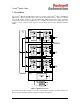
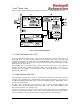
TrustedTM Module T8403 Figure 2 shows a simplified functional block diagram of the TrustedTM 24V dc Digital Input module. Figure 2 Functional Block Diagram 1.1. Field Termination Unit (FTU) The Field Termination Unit (FTU) is the section of the I/O module that connects all three FIUs to a single field device. The FTU primarily contains passive components necessary for front-end signal TM conditioning, field signal over-voltage protection, and EMI/RFI filtering.
TrustedTM Module T8403 1.3. Host Interface Unit (HIU) The HIU is the point of access to the Inter-Module Bus (IMB) for the module. It also provides power distribution and local programmable processing power. The HIU is the only section of the I/O module TM to directly connect to the IMB backplane. The HIU is common to most Trusted I/O types and has type dependent and product range common functions. Each HIU contains three independent slices, commonly referred to as A, B, and C.
TrustedTM Module T8403 1.5. Line Monitoring Thresholds The module determines the contact state and line fault status by comparing the input voltage level to four user programmed thresholds and two fixed (minimum and maximum) thresholds. A “Contact Indeterminate” region is defined between the contact Closed and Open states to account for marginal faults in the external wiring or in the IFIU.
TrustedTM Module T8403 The module biases each input channel by means of a 5kΩ (typical for 24V dc digital inputs) termination resistor to the 0V reference of the module input circuitry. In the absence of any line fault, the zener diodes used for line monitoring purposes form a voltage divider with this termination resistor in the module.
TrustedTM Module T8403 2. Installation 2.1. Module Insertion/Removal CAUTION: The module contains static sensitive parts. Static handling precautions must be observed. Specifically ensure that exposed connector pins are not touched. Under no circumstances should the module housing be removed. Before installation, visually inspect the module for damage. Ensure that the module housing appears undamaged and inspect the I/O connector at the back of the module for bent pins.
TrustedTM Module T8403 2.3.
TrustedTM Module T8403 2.4. TrustedTM Module Polarisation/Keying. All TrustedTM Modules have been Keyed to prevent insertion into the wrong position within a chassis. The polarisation comprises two parts. The module and the associated field cable. Each module type has been keyed during manufacture.
TrustedTM Module T8403 3. Application 3.1. Module Configuration There is no configuration required to the physical input module. All configurable characteristics of the module are performed using tools on the EWS and become part of the application or system.ini file that is loaded into the TMR Processor. The TMR Processor automatically configures the input module after applications are downloaded and during Active/Standby changeover.
TrustedTM Module T8403 OEM Parameter Description Notes TICS_CHASSIS The number of the TrustedTM Chassis where the primary I/O module is installed The Trusted Controller Chassis is 1, and TrustedTM Expander Chassis are 2 to 15 TICS_SLOT The slot number in the chassis where the primary I/O module is installed The I/O module slots in the Trusted Controller chassis are numbered from 1 to 8.
TrustedTM Module T8403 Value Description 7 Unknown 5 Short circuit 4 Closed contact 3 Indeterminate 2 Open contact 1 Open circuit Table 7 Rack 2: STATE Output descriptions The input channel has a value 7 (Unknown) when: 1. The input channel cannot be correctly measured by two or more slices of the TMR input module. 2. The TMR Processor detects a 2oo3 channel discrepancy between the three slices of the TMR input module. 3.
TrustedTM Module T8403 When the TMR Processor detects a 2oo3 channel fault or discrepancy, or if the input module is simulated, the input voltage numeric value is reported as –2048. 3.2.4. Rack 4: SPARE This rack is reserved for future used and is included to promote consistency with other TrustedTM I/O modules. 3.2.5.
TrustedTM Module T8403 3.2.7.
TrustedTM Module T8403 Each input within the housekeeping rack is reported as an integer. In general, the application engineer will not normally require these inputs. They are provided to aid fault finding and diagnosis and are often used for reporting and display purposes. If a slice is Fatal, then all reported housekeeping inputs are set to zero. 3.2.8.
TrustedTM Module T8403 Bit 7 6 5 4 3 Standby Module Ejector open FCR C Healthy 2 1 0 FCR B Healthy FCR A Healthy Active Module FCR B Healthy FCR A Healthy Ejectors open FCR C Healthy Table 15 Rack 8: FCR bit Descriptions The ‘Primary Module is active’ channel is set to non-zero if the primary module is the current active module, i.e. the active module is in the chassis and slot numbers defined within the OEM parameters.
TrustedTM Module T8403 4. Operation 4.1. Front Panel Status LEDs on the front of the module provide visual indications of the module’s operational status and field input status. Each LED is a tri-colour LED of which for normal operation, only two colours are used; red and green. Located at the top and bottom of each module is an ejector lever that is used to remove the module from the chassis. Limit switches detect the open/closed position of the ejector levers.
TrustedTM Module T8403 4.2. Module Status LEDS There are six module status LEDs on the module front panel; three Healthy, one Active, one Standby, and one Educated. The Healthy indicators are controlled directly by each module slice. The Active, Standby, and Educated indicators are controlled by the FPU. The FPU receives data from each of the module slices. The FPU performs a 2-oo-3 vote on each data bit from the slices and sets the indicators accordingly.
TrustedTM Module T8403 4.3. I/O Status LEDs There are 40 input channel status LEDs on the module front panel, one for each field input. These indicators are controlled by the FPU. The FPU receives data from each of the module slices. The FPU performs a 2-oo-3 vote on each data bit from the slices and sets the indicators accordingly. The input status LED mode is dependent upon the voltage level of the field I/O signal.
TrustedTM Module T8403 5. Fault Finding and Maintenance 5.1. Fault Reporting Input module faults are reported to the user through visual indicators (LEDs) on the front panel of the module. Faults are also reported via status variables which may be automatically monitored in the application programs, and external system communications interfaces. There are generally two types of faults that must be remedied by the user; external wiring and module faults.
TrustedTM Module T8403 5.4. Companion Slot For a Companion Slot configuration, two adjacent slots in a TrustedTM Chassis are configured for the same input module function. One slot is the primary slot and the other a unique secondary (or spare) TM slot. The two slots are joined at the rear of the Trusted Chassis with a double-wide I/O Interface Cable that connects both slots to common field wiring terminations.
TrustedTM Module T8403 5.7. Transfer between Active and Standby Modules The TMR Processor is responsible for managing a pair of I/O modules through an active/standby changeover. The following rules apply to active/standby changeovers, though the TMR Processor and not the I/O module enforce them: • The user must define the primary, and optionally the secondary, I/O module location for each I/O module pair.
TrustedTM Module T8403 6. Specifications System Supply Voltage Range 20 to 32V dc Number of Inputs 40 Channels Input Voltage Measurement Range ±40V dc Maximum Withstanding ±50V dc Input voltage monitor absolute accuracy 0.5V dc Full Scale Sample Update Time 0.