
User Manual

Trusted
TM
120Vdc Digital Input FTA T8821
Issue 6 Feb 08 PD-T8821 4
Table of Contents
1. Description...................................................................................................................................7
2. Installation....................................................................................................................................8
3. Associated Cable Selection .........................................................................................................8
4. Assembly Pinout Connections .....................................................................................................9
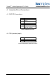
4.1. PWR TB Connections..................................................................................................................9
4.2. TB3 (Auxiliary Input) ....................................................................................................................9
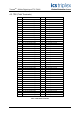
4.3. TB2 (Field Terminals) ................................................................................................................10
4.4. SK1 and SK2 .............................................................................................................................11
5. Specifications.............................................................................................................................12
Figures
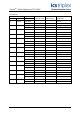
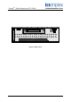
Figure 1 T8821 Layout..............................................................................................................................3
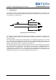
Figure 2 Single Channel Schematic .........................................................................................................7
Tab l e s
Table 1 PWR TB Connections .................................................................................................................9
Table 2 TB3 (Auxiliary Input) Connections ...............................................................................................9
Table 3 TB2 Field Terminals ..................................................................................................................10
Table 4 SK1 and SK2 Connections ........................................................................................................11