TrustedTM PD-T8448 TrustedTM TMR Zone Interface Module – 40 Channel Introduction TM The Trusted TMR Zone Interface module has been designed to provide a configurable interface specifically for use in Fire and Gas protection systems. The module interfaces to up to 40 Fire and Gas field device inputs or actuators. Each of the 40 I/O Channels can be individually configured as Analogue Input, Digital Input or Digital Output to provide all of the interfaces needed to protect one or more Fire and Gas Zones.
TrustedTM Module T8448 Issue Record Issue Number Date Revised by 7 July 05 J W Clark Technical Check Authorised by Modification Reformat Sect 3 Application Resistor Sect 1.5 Default Thresholds added.
TrustedTM Module T8448 This page is intentionally blank Issue 14 Apr 10 PD-T8448 3
TrustedTM Module T8448 Table of Contents 1. Description ...................................................................................................................................9 1.1. Field Termination Unit (FTU) .....................................................................................................10 1.2. Field Interface Unit (FIU) ...........................................................................................................10 1.3. Host Interface Unit (HIU) ....
TrustedTM Module T8448 4. Operation ...................................................................................................................................32 4.1. Front Panel ................................................................................................................................32 4.2. Module Status LEDs ..................................................................................................................33 4.3. I/O Status Indicators ...................
TrustedTM Module T8448 Figures Figure 1 Module Architecture....................................................................................................................9 Figure 2 Function Block Diagram ...........................................................................................................10 Figure 3 Output Switch Structure............................................................................................................13 Figure 4 Simplified Switch Circuit Diagram ......
TrustedTM Module T8448 Notice The content of this document is confidential to ICS Triplex Technology Ltd. companies and their partners. It may not be given away, lent, resold, hired out or made available to a third party for any purpose without the written consent of ICS Triplex Technology Ltd. This document contains proprietary information that is protected by copyright. All rights are reserved.
TrustedTM Module T8448 Revision and Updating Policy All new and revised information pertinent to this document shall be issued by ICS Triplex Technology Ltd. and shall be incorporated into this document in accordance with the enclosed instructions. The change is to be recorded on the Amendment Record of this document.
TrustedTM Module T8448 1. Description TM The TMR Zone Interface module is a member of the Trusted range of Input/Output (I/O) modules. TM All Trusted I/O modules share common functionality and form. At the most general level, all I/O modules interface to the Inter-Module Bus (IMB) which provides power and allows communication with the TMR Processor. In addition, all modules have a field interface that is used to connect to module specific signals in the field.
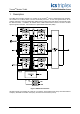
TrustedTM Module T8448 TM Figure 2 shows a simplified block diagram of the Trusted HIU OFIU Failsafe Bias Control Internal Voting Bus A Slice Power Supply Bus Interface Slice Control Stamp TimeA TMR Intermodule Bus N.C. B Diagnostic Monitor Slice B N.O. N.C. Field Logic Control Slice Power Supply Slice Control Stamp TimeB N.O. C Diagnostic Monitor Slice C N.O. Field Interface Protection Circuit N.C.
TrustedTM Module T8448 1.3. Host Interface Unit (HIU) The HIU is the point of access to the Inter-Module Bus (IMB) for the module. It also provides power distribution and local programmable processing power. The HIU is the only section of the I/O module to directly connect to the IMB backplane. The HIU is common to most high integrity I/O types and has type dependent and product range common functions. Each HIU contains three independent slices, commonly referred to as A, B, and C.
TrustedTM Module T8448 1.6. Housekeeping The Zone Interface Module automatically performs local measurements of several on-board signals that can be used for detailed troubleshooting and verification of module operating characteristics. Measurements are made within each slice’s HIU and FIU. 1.7. Fault Detection and Testing From the IMB to the field connector, the I/O module contains extensive fault detection and integrity testing. Most testing is performed in a non-interfering mode.
TrustedTM Module T8448 1.9. Output Switch Structure The Zone Interface Module provides a TMR switch topology where the load is driven by a total of three fully monitored, fail-safe (6 element) switch channels, one physically resident on each OFIU in the module. Any single switch or entire slice failure is designed to leave two of the three fail-safe switch channels operational to power the load. Figure 3 Output Switch Structure The upper switches as shown in Figure 3 are denoted as N.O.
TrustedTM Module T8448 Figure 4 Simplified Switch Circuit Diagram A resistor provides a means of continuously monitoring the switch current. A signal transistor is used to drive the gate of Switch 2. It provides Switch 2 with a negative gate voltage, to minimize it’s on resistance, and serves to hold Switch 2 on in the event that the secondary gate control loses power.
TrustedTM Module T8448 The output current is monitored by the DSP. Sustained over current conditions cause the DSP to deenergise the associated output. Once the fault has been corrected, the latched de-energised state can be reset by turning off the logical output signal to the module and pressing the system fault reset button. The output also includes a non-replaceable fusible link for absolute protection. 1.9.3.
TrustedTM Module T8448 1.11. Input Interfaces Each channel selected as an input is provided with three A/D converters which monitor the voltage at the input connection. These are the same A/D converters which are used to determine channel state in the output configuration. Each input is a high impedance channel and measures from 0 to 30 V. If current is to be measured, the input must be conditioned with an external resistor. This resistor is mounted on the 8842 Versatile Field Termination Assembly.
TrustedTM Module T8448 2. Installation 2.1. Module Insertion and Removal CAUTION: The module contains static sensitive parts. static handling precautions must be observed. Specifically ensure that exposed connector pins ARE NOT TOUCHED. Under no circumstances should the module housing BE REMOVED. Before installation, visually inspect the module for damage. Ensure that the module housing appears undamaged and inspect the I/O connector at the back of the module for bent pins.
TrustedTM Module T8448 2.4.
TrustedTM Module T8448 2.5. TrustedTM Module Polarisation/Keying. TM All Trusted Modules have been Keyed to prevent insertion into the wrong position within a chassis. The polarisation comprises two parts. The module and the associated field cable. Each module type has been keyed during manufacture.
TrustedTM Module T8448 3. Application The Zone Interface Module has been designed to provide a cost effective and high integrity interface with a Fire and Gas Zone. Each Zone within an application will have a unique combination of signals. In order to reduce the amount of hardware required, the Zone Interface has been made configurable using a simple software configuration package. The Zone Interface Module operates in conjunction TM with the Trusted Versatile Field Termination Assembly 8842.
TrustedTM Module T8448 3.1. Module Configuration There is no configuration required to the physical module. All configurable characteristics of the module are performed using tools on the EWS and become part of the application or system.ini file that is loaded into the TMR Processor. The TMR Processor automatically configures the module after applications are downloaded and during Active/Standby changeover. The IEC1131 TOOLSET provides the main interface to configure the Zone Interface module.
TrustedTM Module T8448 3.2. T8448 Complex Equipment Definition The 8448 I/O Complex Equipment Definition includes 10 I/O boards, referenced numerically by rack number. Rack I/O Board Description Data Type Direction No.
TrustedTM Module T8448 3.2.1. Rack 1: DO This board provides the connection to the logical output control signal for each of the field outputs. Channel Description 1 Field output channel 1 logical state 2 Field output channel 2 logical state 40 Field output channel 40 logical state Table 5 Rack 1: DO descriptions The user application should set the output control signal to true (logic ‘1’) to turn ON or energise an output, and false (logic ‘0’) to turn OFF or de-energise an output. 3.2.2.
TrustedTM Module T8448 The least significant 3-bits indicate the operational state of the channel. When configured as an output, the states have the following meaning. Value Description 7 Channel Fault 6 Field fault (e.g.
TrustedTM Module T8448 3.2.3. Rack 3: AI The AI board returns the field loop voltage measured by the module. This is used for analogue and digital inputs, and also for monitoring outputs. Channel Description 1 Field channel 1 voltage 2 Field channel 2 voltage 40 Field channel 40 voltage Table 9 Rack 3: AI bit descriptions The voltage is the median value taken from the triplicated module. The voltage level is reported as an 1 integer, with the units being /500V.
TrustedTM Module T8448 3.2.5. Rack 5: LINE_FLT Channel Description 1 Field channel 1 line fault 2 Field channel 2 line fault 40 Field channel 40 line fault Table 11 Rack 5: LINE_FLT bit descriptions The line fault input state is reported as true (logic ‘1’) for a line fault condition (open circuit, short circuit, and no field supply voltage). The logic state is the majority voted value. 3.2.6.
TrustedTM Module T8448 3.2.7.
TrustedTM Module T8448 Each input within the housekeeping rack is reported as an integer. In general, the application engineer will not normally require these inputs. They are provided to aid fault finding and diagnosis and may be used for reporting and display purposes. If a slice is Fatal, then all reported housekeeping inputs are set to zero. 3.2.8.
TrustedTM Module T8448 The Active and Standby Module Mode is an integer indicating the current operating mode of the associated module. The value indicates the current internal operating mode of the module. Value Module Mode 5 Shutdown 4 Maintain 3 Active 2 Standby 1 Configuration 0 Unknown, no module present Table 15 Rack 8: INFO bit descriptions The FCR Status channel reports the fault status of the active and standby modules.
TrustedTM Module T8448 3.2.9. Rack 9: THRSHIN This board provides the threshold feedback data. Channel Description 1 Module channel number 2 LOW-LOW falling Threshold 3 LOW-LOW rising Threshold 4 LOW falling Threshold 5 LOW rising Threshold 6 HIGH falling Threshold 7 HIGH rising Threshold 8 HIGH-HIGH falling Threshold 9 HIGH-HIGH rising Threshold Table 17 Rack 9: THRSHIN descriptions The data is updated as a result of commands issued through rack 10.
TrustedTM Module T8448 The module channel number may be 1 to 40. The thresholds relate to the channel voltages returned in rack 3. Channel 1 is used to control writing the threshold data specified in channels 4 to 11 to the module channel specified in channel 3. The threshold data will be echoed back in rack 9. Channel 2 is used to control reading the thresholds of the module channel specified in channel 3. The thresholds will be reported in rack 9.
TrustedTM Module T8448 4. Operation 4.1. Front Panel Status indicators on the front panel of the module provide visual indications of the module’s operational status and field status. Each indicator is a bicolour LED. Located at the top and bottom of each module is an ejector lever that is used to remove the module from the chassis. Limit switches detect the open/closed position of the ejector levers.
TrustedTM Module T8448 4.2. Module Status LEDs There are six module status indicators on the module front panel: three Healthy, one Active, one Standby, and one Educated. The Healthy indicators are controlled directly by each module slice. The Active, Standby, and Educated indicators are controlled by the FPU. The FPU receives data from each of the module slices. The FPU performs a 2-oo-3 vote on each data bit from the slices and sets the indicators accordingly.
TrustedTM Module T8448 4.3. I/O Status Indicators There are 40 channel status indicators on the module front panel, one for each field input/output. These indicators are controlled by the FPU. The FPU receives data from each of the module slices. The FPU performs a 2-oo-3 vote on each data bit from the slices and sets the indicators accordingly. The input/output status indicator mode is dependent upon the numerical state of the channel.
TrustedTM Module T8448 5. Fault Finding and Maintenance 5.1. Fault Reporting Zone Interface Module faults are reported to the user through visual indicators on the front panel of the module and through status variables which may be automatically monitored in the application programs and external system communications interfaces. There are generally two types of faults that must be remedied by the user: external wiring and module faults.
TrustedTM Module T8448 5.4. Companion Slot TM For a Companion Slot configuration, two adjacent slots in a Trusted Chassis are configured for the same input module function. One slot is the primary slot and the other a unique secondary (or spare) TM slot. The two slots are joined at the rear of the Trusted Chassis with a double-width I/O Interface Cable that connects both slots to common field wiring terminations.
TrustedTM Module T8448 5.7. Transfer between Active and Standby Modules The TMR Processor is responsible for managing a pair of I/O modules through an active/standby changeover. The following rules apply to active/standby changeovers, though the TMR Processor and not the I/O module enforce them: • The user must define the primary, and optionally the secondary, I/O module location for each I/O module pair.
TrustedTM Module T8448 6. Specifications Common Features System Supply Voltage Range 20 to 32Vdc Circuit Type Fault tolerant, fully triplicated with optional line monitoring Number of Channels 40 Channels Independent Power Groups 5 each of 8 channels Power Consumption System Supply (24V) 24W Field Common Isolation Sustained Working Maximum Withstanding ±250V dc ±2.
TrustedTM Module T8448 This page is intentionally blank Issue 14 Apr 10 PD-T8448 39