
User's Manual


ROCKWELL COLLINS
COMPONENT MAINTENANCE MANUAL with IPL
TDR-94, PART NO 622-9352
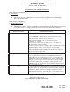
STEP PROCEDURE DESIRED RESULTS
2.13
(cont)
e. Verify that the two recorded amplitudes are with .1 V of each
other. If necessary, readjust the higher voltage downward with
A7R178 or A7R179 (whichever is applicable) until the two
voltages are with .1 V of each other.
N
OTE: If readjustment of A7R178 or A7R179 was necessary,
then the MTL for the top or bottom channel must
also be readjusted in accordance with step 2.4 or
2.10 (whichever is appropriate).
The difference between the
two recorded voltages is 0 ±
0.1 V.
2.14 a. Set the MODE-S Test Set signal strength for -27 dBm.
b. Adjust A6R117 on the Video Processor board while monitoring
the positive end of A6C59 with the oscilloscope.
The obser ved di tch-slope
waveform resulting from P1 is
16.2±.2μswideatitsbase.
2.15
N
OTE: Use extreme care while making the adjustments in steps
2.15 through 2.17. Make the DPSK trimmer capacitor
adjustments in very small increments. These adjustments
are critical to the performance of the TDR-94/94D.
a. To align the DPSK Demodulator VCO, interrogate the bottom
channel with MODE-S ONLY ALL-CALL interrogations having
a signal strength of -50 dBm.
b. Adjust the interrogation center frequency above 1030 MHz
until the reply rate decreases to 90%. Record this frequency
as the upper limit.
Upper Frequency limit: ____
MHz
c. Adjust the interrogation center frequency below 1030 MHz until
the reply rate decreases to 90%. Record this center frequency
as the lower frequency limit .
Lower Frequency limit: ____
MHz
d. Adjust A7R223 to a level where the upper and lower frequency
limits are equidistant from the 1030 MHz center frequency.
The upper frequency limit
must not be less than 1030.6
MHz and the lower frequency
limit must not be greater than
1029.4 MHz
2.16 a. To align the DPSK 60 MHz BPF interrogate the bottom channel
with MODE-S ONLY ALL-CALL interrogations having a signal
strength of -70 dBm and a center frequency of 1030.0 MHz.
b. Slowly adjust A7C110 while monitoring A7J7-37 with the
oscilloscope.
A7C110 is adjusted for the
cleanest and most square
signal pulses at A7J7-37.
Alignment Procedure Cont.
Table 1002/Table 34-50-96-99A-010-A01
34-50-96
Page 1079
May 18/06