
Product Info


PTR for VHF-4000 and VDL-2000 Data Radios
______________________________________________________________________
______
©2000 Rockwell Collins, Inc Page 10 of 61
4.5 TRANSMIT DUTY CYCLE
20 %, 30 seconds maximum single transmit duration
5.
Test Definitions and Information
• In transmit mode, the antenna output shall be terminated in 50
ohm load and the sidetone audio output terminated in 600 ohm
load. In receive mode, receiver and data audio outputs are
terminated in 600 ohm load.
• All receiver RF levels are in dBm at UUT antenna input.
• Upper limit of operation at ICAO channel 136.990 applies for
some units. Disregard operation beyond this frequency in any
alignment or tests where frequencies exceeding this limit are
specified.
• Connect TX_Mode_Indicator (VHF-4000 Pin 47, VDL-2000 Pin 3)
to 27.5 Vdc through a 270 ohm, ½ watt load.
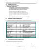
5.1 STANDARD DISCRETE CONFIGURATION
The “Standard Discrete Configuration” is defined as the following configuration of the input discretes:
DISCRETE VHF-4000
Pin #
VDL-2000
Pin #
STATUS
PTT_Sel 41 35 Open (Receive mode)
Simulcom_Cntl_1_Sel
Simulcom_Cntl_2_Sel
42
46
16
34
Open (Attenuator disabled)
Open
RIU_Installed_Sel 43 NA Open (RIU not installed)
All_Call_Dsbl_Set 44 NA Open (All-Call enabled)
Voice/Data_Sel 45 17 Open (Voice mode)
Burst_Tune_Sell 49 NA Open (Continuous tuning)
ARINC/CSDB Select 50 NA Open (ARINC-429 control selected)
Port_C_Sel 51 NA Open (ARINC 429 Input Port C not
selected)
RX_Comp_Dsbl_Sel 52 NA Open (Receive compressor disabled)
Port_A/B_Sel 55 NA Open (ARINC 429 Input Port B
selected)
Unit_ID_A_Sel
Unit_ID_B_Sel
56
62
15
18
Open (All-Call enabled *)
Open
WOW_Sel 57 14 Open (Weight on Wheels not selected)
Data_Load_Enbl_Sel 61 29 Open (Data Load disabled)
SYSTEM_ON_F NA 27 Gnd (Transceiver On)
5.2 STANDARD RF GENERATOR CONFIGURATION
The “Standard RF Generator Configuration” is defined as follows:
Generator set to the frequency defined at time of reference, amplitude modulated
by a 1 kHz sine wave at a modulation level of 30%, and a RF level of –47 dBm.